2 upper range value [20ma]; span 100, Probe lenght and measuring range – Tecfluid LTDR Series User Manual
Page 10
10
the LED will change to blinking green.
Tighten the housing cover properly by turning it clockwise.
7
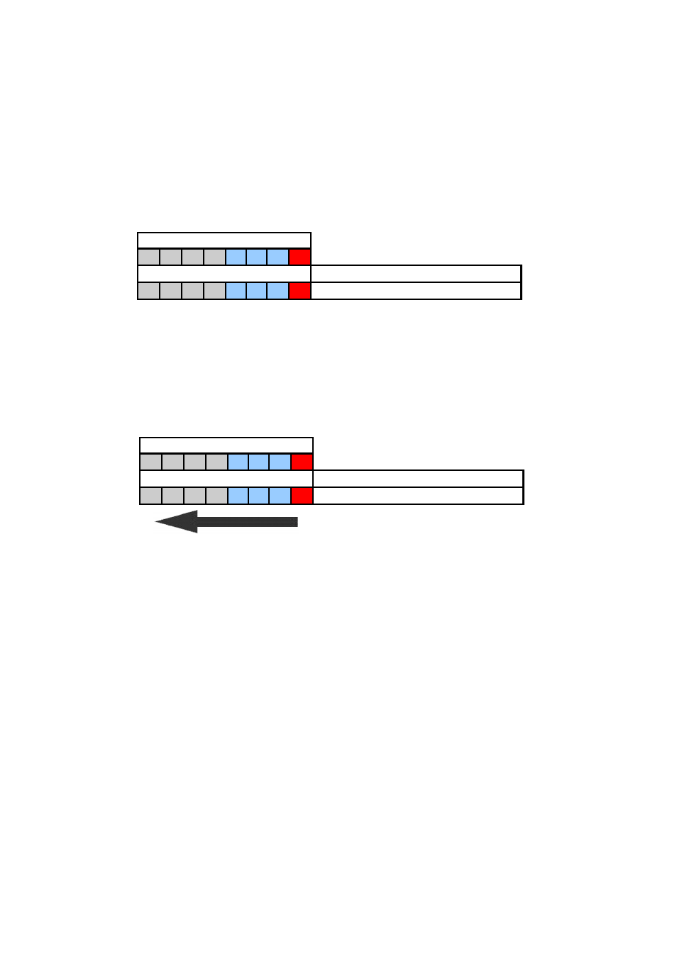
PROBE LENGTH AND MEASURING RANGE
According with the figure 10, the reference point for definition of the probe length [L] is
always the sealing surface of the connection thread. The probe length [L] is an important
mechanical dimension which is needed to make sure the probe physically fits into the tank
at the anticipated mounting location; it is not equal to the actual measuring range [M] of
the sensor!
LTDR level sensors have small inactive areas at top [I1] and bottom [I2] of the probe.
Those are due to the presence of unavoidable signal disturbances at both ends of the
probe. In these inactive areas the measurements are non-linear or have reduced
accuracy. Therefore, it is not recommended to actually measure level within those inactive
areas. Their length depends on the probe type and the reflectivity (i.e. dielectric constant)
of the liquid to be measured.
The measuring range [M] of LTDR extends between the top and bottom inactive areas of
the probe; this is the area in which LTDR will have the specified measurement
performance. It is recommended that the maximum and minimum liquid levels to be
measured in the tank are actually within the measuring range [M] of the sensor. The span
LED will remain green briefly while the lower range value setting is being executed.
Once it has been executed successfully, the LED will return to blinking alternately green
and red.
6.2
Upper range value [20mA]; SPAN 100%
Raise the liquid inside the tank up to the level where you want to position the upper
range value [20mA]; span 100%.
It is recommended that the upper range value stays within the measuring range [M]
(see figure 10).
Change DIP switch position 3 to on/1.
DIP SWITCH POSITION
1
2
3
4
5
6
7
8
DIP SWITCH SETTINGS
DESCRIPTION
0
0
1
0
0
0
1
1
upper range value [20mA]; SPAN 100%
DIP SWITCH POSITION
1
2
3
4
5
6
7
8
DIP SWITCH SETTINGS
DESCRIPTION
0
0
0
0
0
0
0
0 measuring
mode
Figure 9
Press the push button.
LED will remain green briefly while the upper range value setting is being executed.
Once it has been executed successfully, the LED will return to blinking alternately green
and red.
Set all the DIP switch positions to 0 as indicated in figure 9. Start from position 1 and
move towards position 8.