Control elements – Tecfluid LTDR Series User Manual
Page 6
6
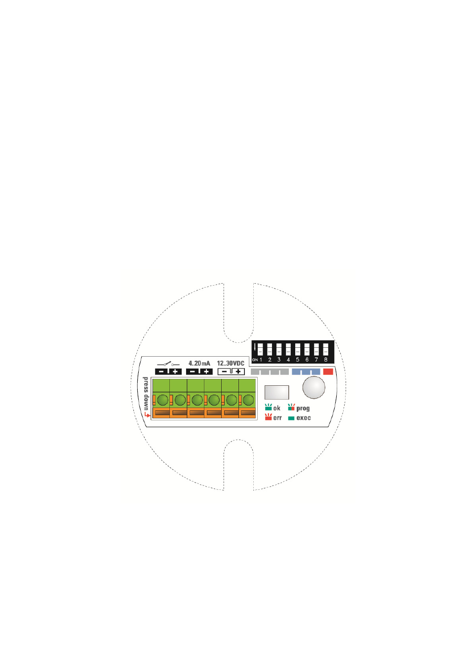
The DIP switch has 8 small white levers. Small numbers from 1 to 8 are printed
underneath the levers: they indicate the DIP switch positions and correspond to the ones
in figure 5.
The upper position of a lever is off/0 and the lower position is on/1. On the left side of the
DIP switch is also a small indication of the on/1 state.
The off/0 and on/1 states of the DIP switch correspond to the 0/1 indications in figure 5.
The upper sticker on the black plastic cartridge shows three colour segments close to the
DIP switch: red, gray, and blue; they correspond to the coloured rows in figure 5.
Pull the cable back, but make sure its mantle does not retract into the cable gland.
Tighten the cable gland to ensure proper sealing function.
Switch on the power supply for the sensor.
The sensor LED should start blinking green within 6 seconds after connecting the power
(during this start-up time the LED is off). The blinking green LED indicates that the sensor
is in measuring mode and working correctly.
Do not tighten the housing cover yet. Some basic configuration is still to be done…
LTDR’s electronic is galvanically completely insulated from its inputs/outputs and the tank
potential; thus avoiding any problems from electrochemical corrosion protection of the
tank.
4 CONTROL
ELEMENTS
Basic configuration of LTDR can be done directly on the device via three control
elements: a DIP switch, a single push button and a LED for visual feedback. All settings
required to get LTDR fully operational can be performed directly on the device; or LTDR
can be ordered completely pre-configured.
All three control elements are enclosed in the black plastic cartridge inside the housing.
Figure 4. Control elements