Electrical connection – Tecfluid LTDR Series User Manual
Page 5
5
The coaxial probe is recommended for installing LTDR into a non-metallic tank or open
pit. If that is not possible, a single rod probe can be used when LTDR is mounted into at
least a DN50 metal flange or screwed into a metal sheet with at least Ø150 mm.
3 ELECTRICAL
CONNECTION
Verify that the power supply for the sensor (not supplied) is switched off.
Establish an equipotential connection (potential equalization) between the external earth
terminal of LTDR and the closest ground potential terminal of the tank.
Open the housing cover by turning it counterclockwise.
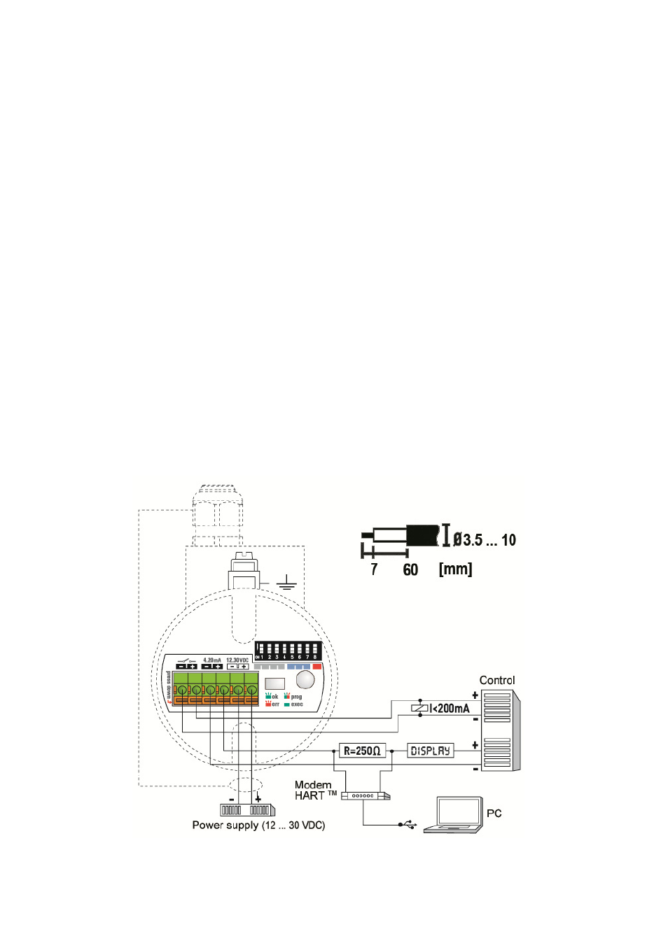
The housing is supplied with two cable glands M16x1,5 apt for cables of Ø 3,5 ... 10 mm.
Loosen the cable gland and pull the cable through the cable gland into the housing. Pull it
far enough to have a convenient length for stripping and handling the cable.
Install cable with a drip loop outside the housing where the bottom of the loop must be
lower than the cable entry of the housing.
Dismantle the cable carefully and strip the wires as indicated on the top right drawing of
thre figure 3.
The stripped wire ends are connected to the sensor electronic via the green screwless,
cage clamp terminal block. It can accommodate stranded and solid wires 0,5…2 mm².
The usage of cable end sleeves with insulation collar is not recommended.
Simply press an orange lever straight down with a small flat tip screwdriver, insert a
stripped wire end into the terminal hole, and release the orange lever; the wire is now
connected.
The upper sticker inside the housing illustrates the inputs and outputs. Connect all wires
accordingly, as indicated in figure 3.
Figure 3. Electrical connection