Operator’s manual df32, 3 fitting the pump head to the machine – Watson-Marlow DF32 User Manual
Page 19
Operator’s manual
DF32
Rev.: 1.03 Date: 2007-03-12 Page 19 of 32
File:
DF32 OM 1.03 EN
Step Action
9
Mount the O-ring (12) to the front part (5).
10
Mount the O-ring (7) on the bearing (11), and mount both in the front part.
11
Fit the front part to the pump housing.
A pin on the pump housing and a hole in the front part indicates correct positioning.
12
Close the pump head by fastening the finger screws (21) firmly.
Note: If the front part is angled during fastening, the pump might not be leak tight.
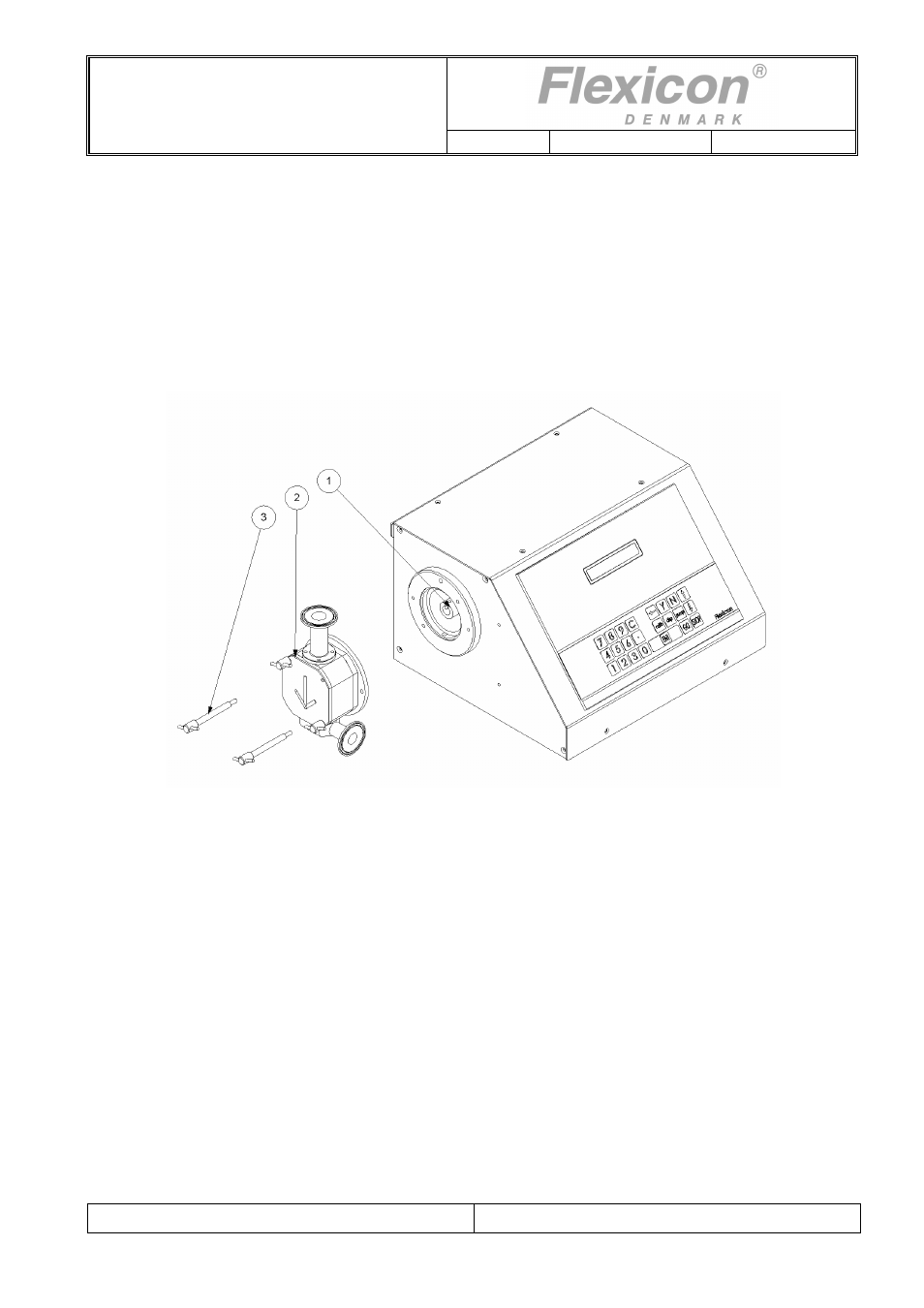
7.3 Fitting the pump head to the machine
Fig. 7.3
Step Action
1
Hold the pump head (2), with the arrow pointing in the desired direction of flow.
2
Align the key (1) on the drive shaft, with the groove on the pump head shaft.
Press the pump head towards the flange on the machine front, and make sure that the pin on the
rear of the pump head fits into the corresponding hole in the flange.
3
Fasten the pump head with the 2 finger screws (3).
4
Set up DF32 with product tubes and filling nozzles.
NOTE!
When a hopper is used for product supplied, the pump head of DF32 must be supported by the
supplied support, for safety reasons. See Fig. 7.4