Operator’s manual df32, 4 installation – Watson-Marlow DF32 User Manual
Page 7
Operator’s manual
DF32
Rev.: 1.03 Date: 2007-03-12 Page 7 of 32
File:
DF32 OM 1.03 EN
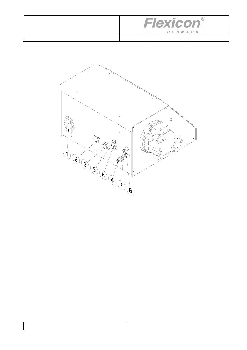
4.4 Installation
DF32 must be placed on a stable bed plate. All connections are on the rear of the machine.
Fig. 4.1
Electrical
connections:
1
The main cable supplied is connected to the integrated main socket (1) in the main isolator, which also
contains master fuses. The plug is connected to an earthed switch.
2
External GO plug for the connection of a foot switch or for an external starting signal.
3
RS-232 plug for printer connection.
Connections of pneumatics:
4
If DF32 is to run with pneumatic equipment, a supply of compressed and dry air should be connected to
the quick release clutch (4).
The female part of the quick release clutch is supplied with the machine, but is not fitted.
Filling nozzles with pneumatic cut-off valves:
5
Nozzles with internal cut-off valve shall be connected to connector 5.
6
Nozzles with external cut-off valve shall be connected to connector 6.
Pneumatically driven diving nozzles:
7
Hoses giving the downward movement should be connected to connector 7,
8
Hoses giving the upward movement should be connected to connector 8.