Operator’s manual df32, 10 interface – Watson-Marlow DF32 User Manual
Page 28
Advertising
Operator’s manual
DF32
Rev.: 1.03 Date: 2007-03-12 Page 28 of 32
File:
DF32 OM 1.03 EN
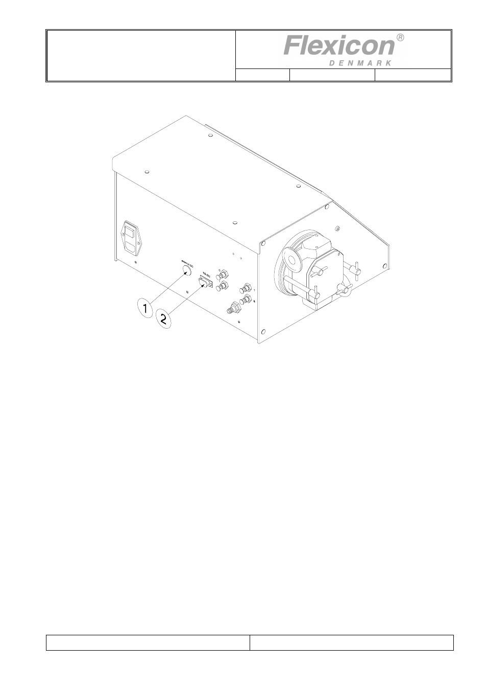
10 Interface
Fig. 10.1
DF32 has two electrical interface connectors.
(1) "External
GO"
(2) RS-232
"External GO" is designed as a 5-pin DIN plug with the following PIN configuration:
PIN 1
Input for start signal. +5 - 50 VDC, min. 100 msec. positive edge-
triggered.
PIN 2: Output, +24 VDC, max. 250 mA.
PIN 3: Ground
PIN 4: Status output, max. +24 VDC, 100 mA.
Pin 4 is grounded via an open collector during filling.
PIN 5: Status output, max. + 24 VDC, 100 mA.
Pin 5 is complementary to Pin 4.
Advertising