Rs-232 connections, Line connection – Westermo TD-22 User Manual
Page 5
25 Pin
Screw
Direction
Name
Description
D-sub
Terminal
DCE-DTE
1
- - -
PE
Protective earth
2
8
TXD
Transmit data
3
7
RXD
Receive data
4
6
RTS
Request to send
5
5
CTS
Clear to send
6
2
DSR
Modem ready
7
1
- - -
SG
Signal ground
8
4
DCD
Data carrier detect
9
Continuous high
10
Continuous low
12
DRS
Speed indication (1200/2400)
15
TXC
Synchronous TXD clock from modem
17
RXC
Synchronous RXD clock from modem
20
3
DTR
Data terminal ready
21
RDL
Request of remote digital loopback
22
9
RI
Ring indicator
23
DRS
Data speed select (1200/2400)
24
EXC
External synchronous clock
25
TI
Test indication signal
6
6177-2203
RS-232 Connections
Pin outs for the 25-pole D-sub and 9-pole screw terminal:
The other pins in the 25-pole D-sub should be left unconnected.
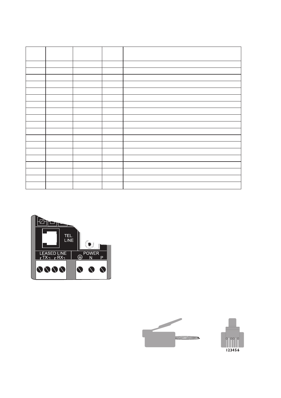
Line connection
The telephone line is connected to the 6-pole RJ-12
connector or to the 4-pole screw block in the bottom
left side.
When using the screw-block a strap plug supplied must
be placed in the RJ-12 connector. If this is not done the
outgoing signal will not be connected to the screw-
block.
←
←
←
←
←
←
←
←
←
←
←
←
←
←
←
←
←
1
:
6
1 2 3
4
2-wire lines are connected to the two middle pins
(3 & 4) in the RJ-12 plug or the TX screws
(1 & 2).
In the UK modems the RJ-12 connection is on pin
2 & 5.
4-wire lines are connected to the screw terminal,
transmitter to TX (1 & 2) and receiver to RX (3 & 4).