Dip switch setup – Westermo TD-22 User Manual
Page 7
8
6177-2203
DIP Switch Setup
Disconnect power before changing DIP-switches.
Take ESD-protection when changing switches.
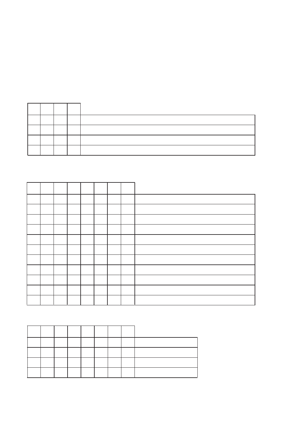
The DIP-switches can be used to provide the following settings.
The DIP-switches are underneath the top lid of the modem. (1 = On, 0 = Off)
Non defined switches will be in off position.
SW1:
4
3
2
1
0
Dial-up line
1
0
Leased line, switch off echo and result code. Answering
1
1
Leased line, switch off echo and result code. Dialling.
1
All commands ignored, including +++
SW2:
8
7
6
5
4
3
2
1
0
SW2:2 to 7 not used
1
For use of SW2:2 to 7
Choice of clock:
Clock source:
0
0
Asynchronous
0
1
Synchronous Ext.
Clock from D-sub pin 24
1
0
Synchronous Int.
The modem creates clock
1
1
Synchronous slave
Clock from line
1
DTR/DSR disconnected (AT&S0&D0&C0)
1
V.25 commands enabled
1
Remote configuration enabled
1
Callback security enabled
8
7
6
5
4
3
2
1
0
4-wire line connection
1
2-wire line connection
0
1
REL-mode disconnected
SW3: