User’s guide – X-Treme Audio XTI User Manual
Page 6
7. The array editor
Use the icon
to insert a new array; click on the selected point on the map and
drag it to the required target point for horizontal pointing.
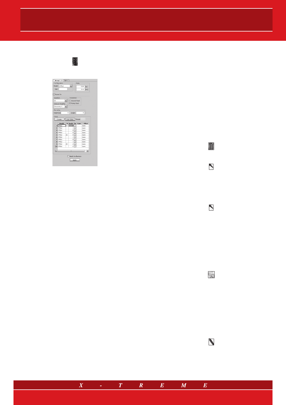
Fig. 6 Array parameter management panel
Once the information in the initial editor is entered, a new editor
window appears on the right side of the workspace, with the fol-
lowing functions and options:
• Configuration: generic array model (XTMISI, XTMLA, etc.) and
possible global deactivation (ON-OFF) of the array.
• Installation: choice between “ground stack” and “flying stack”
installation.
• Height: flying bar height and vertical angle (for flying stacks): they
are both active for flying systems, while the angle is set to 0° for
ground configurations.
• Splay Angles: are the angles between each element and the pre-
vious one (the upper for flying/suspended configurations and the
lower for ground). This data is automatically limited to a well-
defined range depending on the specific speaker geometry.
• Number of elements: for flying systems this number is limited by
the height of the flying bar; symmetrically, a default number of
speakers sets a minimum value for the bar height. The max. cap.
of the flying bar is certified up to 12 upper modules, but the XTI
program can accept a maximum of 16 elements.
• Model: specific model (upper module or subwoofer), and pos-
sible deactivation for each array element. Switching a model to
“subwoofer” automatically turns each box above it (suspended
array) or below (stacked array) into a subwoofer.
• On board amplifier: depending on the model, this allows the user
to decide where on board amplifiers will be placed, influencing the
position of the mass center and the resulting rigging output data;
in this case, filter choice (see next point) will be limited to groups
of equal filters, equal to the number of on board amplifiers.
• Filter: graphic third octave equalizer, chosen from a specific list
for each array model, which simulates the presets provided by
X-Treme Audio along with its products.
• Delay: a delay common for all of the elements (see previous par-
agraph for delay input modality).
• Create: using audience area’s geometry as input data automati-
cally provides a feasible number of array boxes as well as flying
bar height and angle (for flying systems). An autosplay calcula-
tion is included (see below).
• Preset splay arrows: (to scroll splay sets): once array length
and height are chosen (manually or automatically) and when the
audience area design is decided, use these arrows to obtain
varying splay angle configurations, starting with a circular shape
and moving to more progressive curvatures, even a “J” shape.
The common factor of all these configurations is the total cov-
erage angle, meaning the sum of the splay angles (with varia-
tions of few degrees), which depends on the specific audience
geometry. Pushing these arrows will result in forcing the flying
bar angle to its optimum value considering the specific audience
geometry.
• Autosplay: tests all the possible splay sets (introduced at the
previous point), and sets the one giving the best evaluated SPL
distribution on the active audience areas on a straight line point-
ing in the same horizontal direction as the array.
8. Editing and deleting objects
To delete a speaker, an array or an area, left click
then left click the element to be eliminated in the map view.
To move an object activate
(Select tool) and drag the desired element (in the map view).
Otherwise, double click the object and its editing window will ap-
pear allowing you to enter new coordinates.
To adjust speaker target points, it is possible to drag the triangular
arrow associated with each speaker or array, if previously activated
by single clicking
in the plan view. Each time you move the arrow, the target point will
be updated with the new horizontal coordinates of the arrow, and
its height will be set to the listener height in the highest active area
in the new position. If necessary, you can readjust the target point
height by editing the speaker window or changing the state (active
or inactive) of some areas.
To edit existing areas, left click on a vertex to view the coordinate
numbers, then right click to open the editor window.
9. Map and section calculation and viewing
Activating the
icon will calculate the
sound level and make the color-map ap-
pear both in the plan view and in the vertical section view: the
sound level and sonogram also appear (if not hidden by the user)
along the segment of the section (Level and Sonogram).
The map, section, and level that appear are in the frequency range
currently selected on the toolbar.
The level in the map view refers to the listener height level at each
listener area, meaning each area at its height and inclination. This
means normal color discontinuities will be seen between neighbor-
ing areas where height discontinuities are present.
To set a new section segment, select the
icon and draw a line in the plan view: section, level and “sonogram”
will be recalculated and viewed.
To update these values (and not the map view) when segment
is left unchanged (but for example the speaker system setup is
changed), double click on the section view.
6/9