Configuration procedure – H3C Technologies H3C S3100V2 Series Switches User Manual
Page 108
100
•
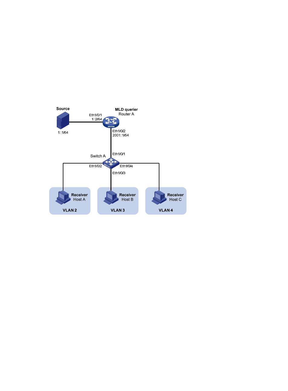
MLDv1 runs on Router A. MLDv1 snooping runs on Switch A. Router A acts as the MLD querier.
•
Switch A’s Ethernet 1/0/1 belongs to VLAN 10, Ethernet 1/0/2 through Ethernet 1/0/4 belong
to VLAN 2 through VLAN 4 respectively, and Host A through Host C are attached to Ethernet
1/0/2 through Ethernet 1/0/4 of Switch A.
•
The IPv6 multicast source sends IPv6 multicast data to IPv6 multicast group FF1E::101. Host A, Host
B, and Host C are receivers of the IPv6 multicast group.
•
Configure the port-based IPv6 multicast VLAN feature so that Router A just sends IPv6 multicast data
to Switch A through the IPv6 multicast VLAN and Switch A forward the IPv6 multicast data to the
receivers that belong to different user VLANs.
Figure 31 Network diagram for port-based IPv6 multicast VLAN configuration
Configuration procedure
1.
Enable IPv6 forwarding and configure IPv6 addresses
Enable IPv6 forwarding on each device and configure the IPv6 address and address prefix for each
interface according to
. The detailed configuration steps are omitted here.
2.
Configure Router A
# Enable IPv6 multicast routing, enable IPv6 PIM-DM on each interface, and enable MLD on the host-side
interface Ethernet 1/0/2.
<RouterA> system-view
[RouterA] multicast ipv6 routing-enable
[RouterA] interface ethernet 1/0/1
[RouterA-Ethernet1/0/1] ipv6 pim dm
[RouterA-Ethernet1/0/1] quit
[RouterA] interface ethernet 1/0/2
[RouterA-Ethernet1/0/2] ipv6 pim dm
[RouterA-Ethernet1/0/2] mld enable
3.
Configure Switch A
# Enable MLD snooping globally.
<SwitchA> system-view