Configuration procedure – H3C Technologies H3C SR8800 User Manual
Page 47
38
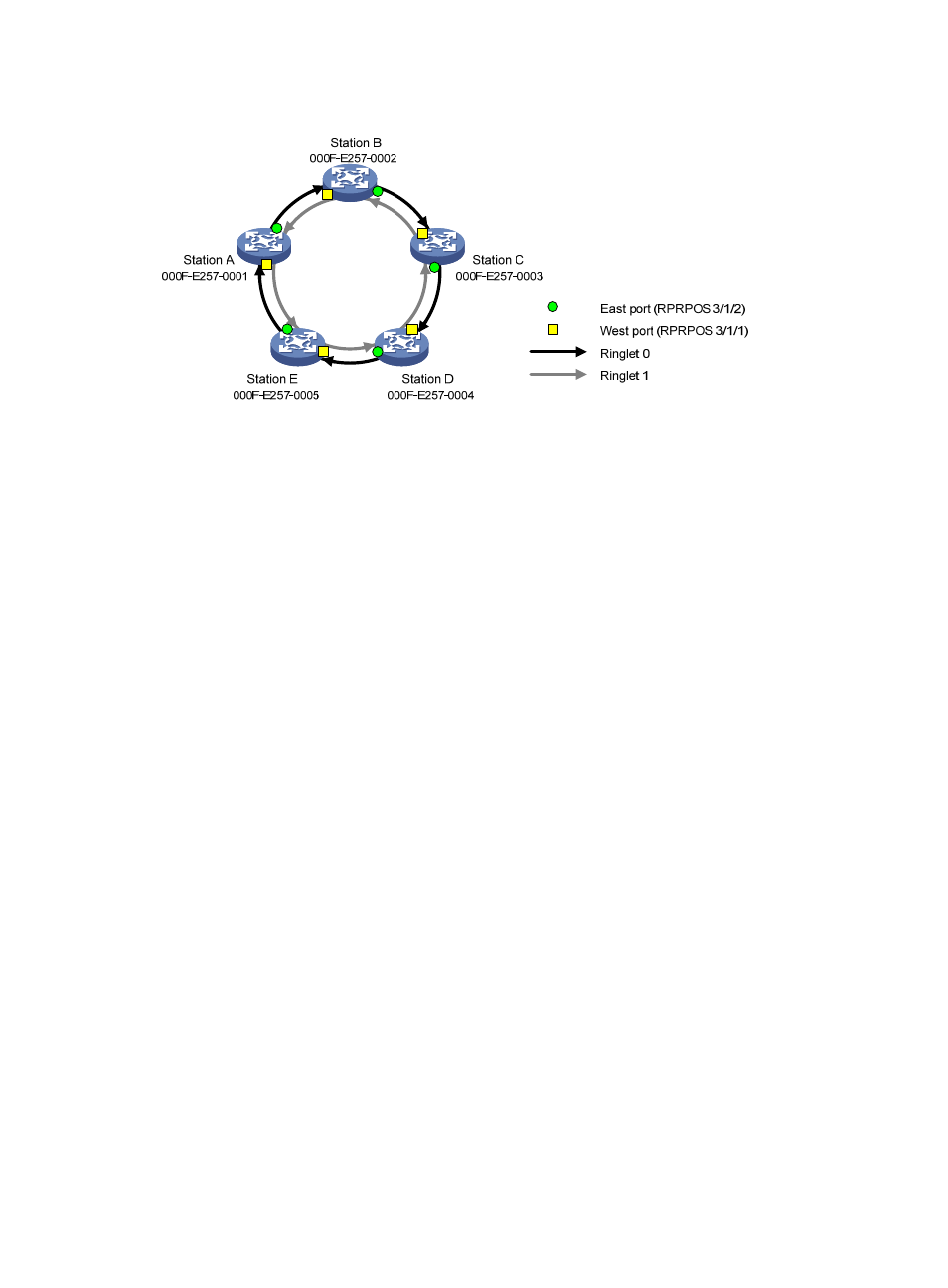
Figure 8 Network diagram
Configuration procedure
1.
Create an RPR logical interface and bind two RPR physical ports to the logical interface:
# On Station A, create Layer 3 RPR logical interface RPR1, and bind RPR physical ports RPRPOS
3/1/1 (the west port) and RPRPOS 3/1/2 (the east port) to RPR 1.
<StationA> system-view
[StationA] interface rpr 1
[StationA-RPR1] rpr bind RPRPOS 3/1/1 ringlet0
[StationA-RPR1] rpr bind RPRPOS 3/1/2 ringlet1
[StationA-RPR1] quit
The configuration steps on Station B, C, D, and E are similar to those on Station A and not shown.
2.
Verify the configuration:
# Display RPR interface binding information on Station A.
[StationA-RPR1] display rpr bind-info
Bind information on interface: RPR1
Smart-connection: Disabled
PHY-Interface Ringlet-ID Role Mate-Port
---------------------------------------------------
RPRPOS3/1/1 Ringlet0 Master Up
RPRPOS3/1/2 Ringlet1 Slave Up
# Display the RPR topology summary on Station A.
[StationA] display rpr topology all summary
Topology information items
Psw:protection state, west Pse:protection state, east
Esw:edge state, west Ese:edge state, east
Wc:wrap protection configured Jp:jumbo frame preferred
Ring-level topology information on interface: RPR1
Ringlet0 Ringlet1 Ring Jumbo-Prefer Topology-Type
-------------------------------------------------
4 4 5 Regular Closed ring
Local station topology information on interface: RPR1