Network requirements, Configuration procedure – H3C Technologies H3C SecPath F1000-E User Manual
Page 36
20
Loadsharing Type: Shar -- Loadsharing, NonS -- Non-Loadsharing
Actor System ID: 0x8000, 000f-e2ff-0001
AGG AGG Partner ID Select Unselect Share
Interface Mode Ports Ports Type
-------------------------------------------------------------------------------
BAGG1 D 0x8000, 000f-e2ff-0002 3 0 Shar
The output shows that link aggregation group 1 is a load shared Layer 2 dynamic aggregation group
and it contains three Selected ports.
Layer 2 Aggregation Load Sharing Configuration Example
Network requirements
As shown in
:
•
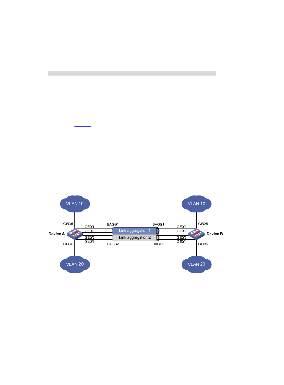
Device A and Device B are connected by their Layer 2 Ethernet interfaces GigabitEthernet 0/1
through GigabitEthernet 0/4.
•
Configure two Layer 2 static aggregation groups (1 and 2) on Device A and Device B respectively,
enable VLAN 10 at one end of the aggregate link to communicate with VLAN 10 at the other end,
and VLAN 20 at one end to communicate with VLAN 20 at the other end.
•
Configure the load sharing criterion for link aggregation group 1 as the source IP addresses of
packets and the load sharing criterion for link aggregation group 2 as the destination IP addresses
of packets to enable traffic to be load-shared across aggregation group member ports.
Figure 6 Network diagram for Layer 2 aggregation load sharing configuration
Configuration procedure
Step1
Configure Device A
# Create VLAN 10, and assign the port GigabitEthernet 0/5 to VLAN 10.
<DeviceA> system-view
[DeviceA] vlan 10
[DeviceA-vlan10] port gigabitethernet 0/5
[DeviceA-vlan10] quit
# Create VLAN 20, and assign the port GigabitEthernet 0/6 to VLAN 20.
<DeviceA> system-view