Cabling, 8937 module – Grass Valley 8937 v.1.0.0 User Manual
Page 12
12
8937/8937D Instruction Manual
Installation
Cabling
8937 Module
Refer to
for cabling the 8937 module. Cabling to and from the
module is done at the back of the Gecko 8900 video frame as described
below.
Note
At the back of every manual are two sets of printed overlay cards that can be
placed over the rear connector BNCs to identify the specific connector func-
tions.
Loop-Through Input
One serial digital component input is provided at differential loop-through
BNCs J9 and J10. If the unused input is not looped to another device, it
should be terminated in 75
Ω
.
Outputs
There are eight outputs for the 8937 module at BNCs J1 through J8. Output
destination equipment should have an input impedance of 75
Ω
unless it
has loop-through inputs, in which case the loop-through inputs must be
terminated into 75
Ω
. All outputs are in phase with the input signal.
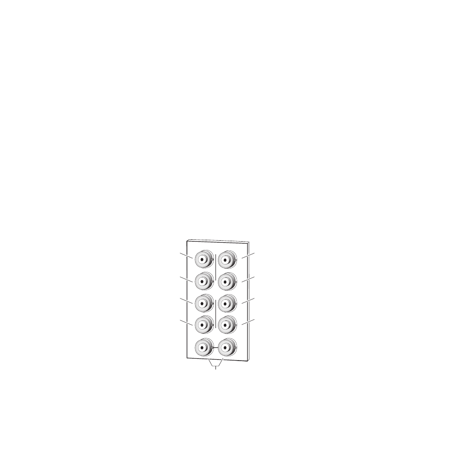
Figure 5. 8937 Rear Input/Output Connectors
J2
J4
J6
J8
J9 J10
SDI Out 8
J3
J5
J7
J2
J1
J4
J6
J8
8270_03
Differential
loop-through
SDI video inputs
SDI Out 1
SDI Out 3
SDI Out 5
SDI Out 2
SDI Out 4
SDI Out 6
SDI Out 7