8737d module – Grass Valley 8937 v.1.0.0 User Manual
Page 13
8937/8937D Instruction Manual
13
Installation
8737D Module
for cabling the 8937D module. Cabling to and from the
module is done at the back of the Gecko 8900 video frame as described
below.
Note
At the back of every manual are two sets of six overlay cards that can be
placed over the rear connector BNCs to identify the specific connector func-
tions.
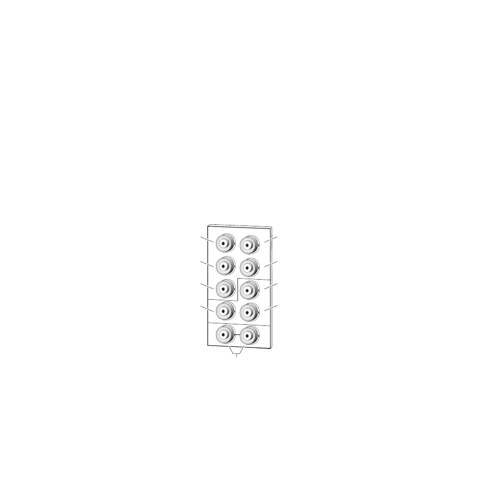
DA 1 Inputs and Outputs
DA 1 provides one serial digital component input at loop-through BNCs J9
and J10. If the unused input is not looped to another device, it should be
terminated in 75
Ω
. The three outputs for DA 1 are from BNCs J6, J7, and
J8. All outputs are in phase with the input signal.
DA 2 Inputs and Outputs
DA 2 provides one terminated serial digital component input at BNC J5.
The four outputs for DA 2 are from BNCs J1, J2, J3, and J4. All outputs are
in phase with the input signal.
Figure 6. 8937D Rear Input/Output Connectors
J2
J4
J6
J8
SDI Out 13
8270_09
SDI In 1
(differential loop-through)
SDI Out 21
SDI In 2
(terminated)
SDI Out 23
SDI Out 22
SDI Out 24
SDI Out 11
SDI Out 12
J9
J10
J3
J5
J7
J2
J1
J4
J6
J8