8964mon module on-board configuration settings, Onboard jumper, For configuration (see – Grass Valley 8964MON User Manual
Page 17
8964MON Instruction Manual
17
Configuration
8964MON Module On-board Configuration Settings
On-board configuration is done on a channel-by-channel basis, there is no
gang mode (apply settings to all channels).
To make a configuration setting, do the following:
1.
Select the channel to be adjusted by pressing pushbutton SW2 to toggle
to the Channel Select Mode (yellow CSM LED on). This allows using
the paddle switch to increment through the channel selections. The
currently selected channel is indicated by the state of the CM1 and CM0
LED. Refer to
for reading LED states.
2.
When the desired channel is active, use pushbutton SW2 to toggle back
to Parameter mode (CSM LED off).
3.
Rotate the Function switch the desired setting.
4.
Move the paddle switch to the up or down position and hold
momentarily to set the desired function (refer to
Onboard Jumper
Jumper JP1 allows (LOC&REM position) or locks out (LOCAL position)
remote control.
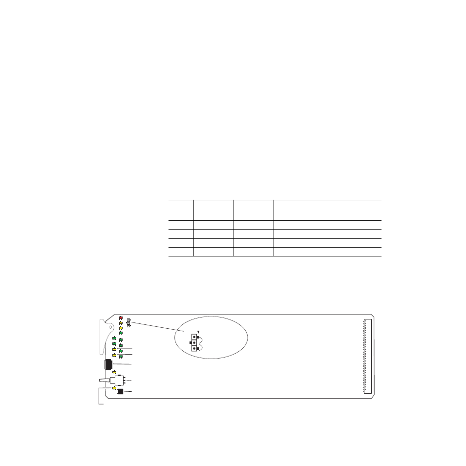
Figure 6. Module Configuration Switches and LEDs
Table 5. Local Rotary and Paddle Switch Functions
Function
Switch
Setting
Paddle
Switch Up
Paddle
Switch Down
Function Description
2
Add setup
No Setup
In 525 mode, add setup to composite output.
4
Increase
Decrease
Adjust composite output gain.
D
Enable
Disable
Enable or disable color bars test signal.
F
–
Recall
Recall Factory Defaults
8367_03
Place jumper in Local position
to lock out remote access.
Function rotary switch
CM1 LED
CM0 LED
Pushbutton switch
Paddle switch
LOC&REM (2–3)
CSM LED
Remote Lockout
LOCAL (1–2)
JP1