Gpi input and output, Notes, Connectors – Grass Valley iMC-Panel-100 v.7.2.9.0 User Manual
Page 56: Button panel, Power
44
Control Panel
Connectors
Consult with your system administrator to determine which options apply to the GPI input
buttons in your iMC-Panel-100 configuration.
GPI Input and Output
A combined GPI input and output button performs 2 functions.
•
The illumination of the button represents the state of a GPI input as for the GPI input but-
tons.
•
Pressing the button toggles the state of a relay, as for the GPI output buttons.
Note that the button displays the state of the designated input, not the designated output.
If necessary, consult with your system administrator to determine which input and output
applies to a button of this type and which display option applies.
Notes
Remember that most of the iMC-Panel-100’s button legends are at the discretion of the config-
urer. They might not be exactly what you see listed in this guide.
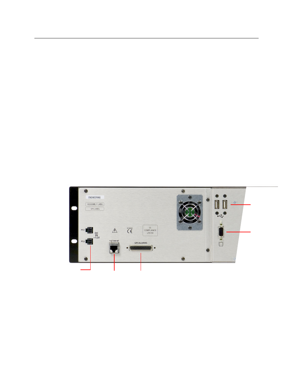
Connectors
At the rear of the iMC-Panel-100’s button panel are 2 power connectors, an Ethernet connector,
two USB connectors, a VGA connector (for the display unit) and a GPI/alarm connector:
Button Panel
Power
There are 2 power connectors, PS1 and PS2, for the sake of redundancy. Only one is required,
but with both, the iMC-Panel-100 will continue uninterrupted operation if one fails.
USB Ports
(2)
(to monitor)
VGA Port
(to monitor)
GPI/Alarms
(DB25)
Ethernet
(RJ-45)
Power Supply
Connectors (2)