Connecting the script viewer system – Grass Valley SCRIPT Viewer News Rev.A User Manual
Page 15
TM
Page 13
© 1999 ParkerVision, Inc. • Install Your SCRIPT Viewer™
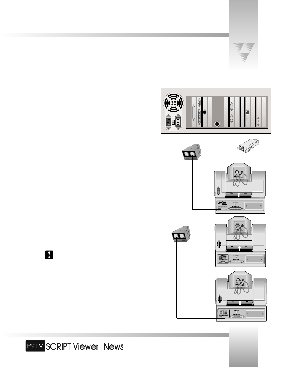
Connecting the SCRIPT Viewer System
Connecting the SCRIPT Viewer CPU to the Cameras
To get full functionality out of your PVTV SCRIPT Viewer, it is necessary to connect the CPU to
your cameras. This RS-485 connection gives the reader the ability to control the text they see
on the displays with a wireless keypad. With the keypad, the reader can adjust the script’s font
size, scroll speed, and scroll direction. They also can load and cue up new scripts, and play and
pause scripts.
To connect the SCRIPT Viewer CPU to the cameras:
1. Locate the 9-Pin RS-485 Port
on the rear panel of the SCRIPT Viewer CPU.
2. Attach the RS-485 adapter
(included with SCRIPT Viewer) to the port.
For Single-Camera Systems:
3. Connect one end of the 25’ RS-485 communications cable (included with SCRIPT
Viewer) to the RS-485 adapter. Connect the other end of the cable to the RS-485
port on the back of the camera.
For Multi-Camera Systems:
3. Connect one end of the 6’ RS-485 communications cable (included with SCRIPT
Viewer) to the RS-485 adapter. Connect the other end of the cable to the single port
on the included T- Connector
.
4. Connect one end of an RS-485 communications cable (there are two included with
SCRIPT Viewer) to one of the remaining ports on the T-Connector. Attach the other
end of the cable to the RS-485 port on the back of the first camera.
When more than one camera is being used, select the one closest to
where the SCRIPT Viewer keypad will be used. Also, verify that the RF
ENABLE switch on the back of the camera is set to ON. The remaining
cameras should have their RF switch OFF.
5. Connect another RS-485 communications cable between the remaining port on the
T-Connector and the single port on a second T-Connector.
6. Connect one end of the second RS-485 communications cable to one of the
remaining ports on the T-Connector. Attach the other end of the cable to the RS-485
port on the back of the next camera.