Connecting the script viewer system – Grass Valley SCRIPT Viewer News Rev.A User Manual
Page 16
TM
Page 14
Installation and Operations Manual • © 1999 ParkerVision, Inc.
Connecting the SCRIPT Viewer System
7. Repeat steps 5 and 6 for each additional camera.
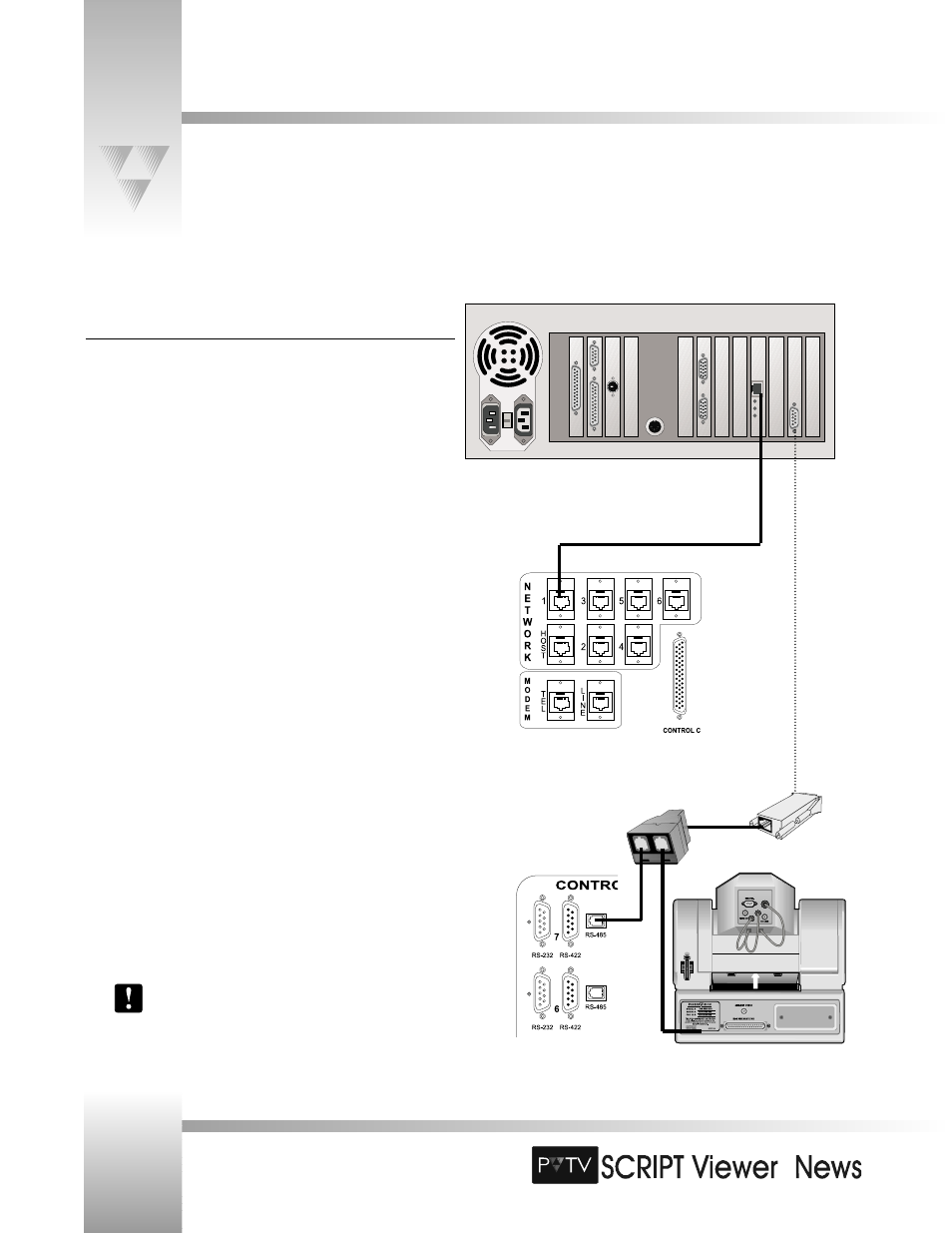
Connecting SCRIPT Viewer to PVTV STUDIO
To control SCRIPT Viewer from within PVTV STUDIO Interface:
1. Locate the Network Communication port
on the rear panel of
the SCRIPT Viewer CPU.
2. Connect one end of the RJ-11 8-pin cable (included with SCRIPT
Viewer) to the Network Communications port.
3. Connect the other end to the NETWORK 1 port
on the rear
panel of the PVTV STUDIO CPU.
To control SCRIPTview displays with wireless keypad:
1. Locate the 9-pin RS-485 port
on the rear panel of the SCRIPT
Viewer CPU.
2. Attach the RS-485 adapter (included with SCRIPT Viewer) to the port.
3. Connect one end of the 6’ RS-485 communications cable (included
with SCRIPT Viewer) to the RS-485 adapter. Connect the other end to
the single port on the included T- Connector.
4. Connect one end of an RS-485 communications cable (there are two
included with SCRIPT Viewer) to one of the remaining ports on the
T-Connector. Attach the other end to one of the RS-485 control ports
on the rear panel of the Serial Control module.
5. Connect another RS-485 communications cable between the
remaining port on the T-Connector and the RS-485 port on the
camera.
6. For each additional camera in your network, use another RS-485
communications cable to connect it to one of the other RS-485
control ports on the Serial Control module.
Please refer to your PVTV STUDIO manuals for further
installation instructions.