Graphics during fk programming – HEIDENHAIN TNC 320 (340 551-02) User Manual
Page 147
HEIDENHAIN TNC 320
147
6.6 P
a
th Cont
ours—FK F
ree Cont
our Pr
ogr
a
mming
Graphics during FK programming
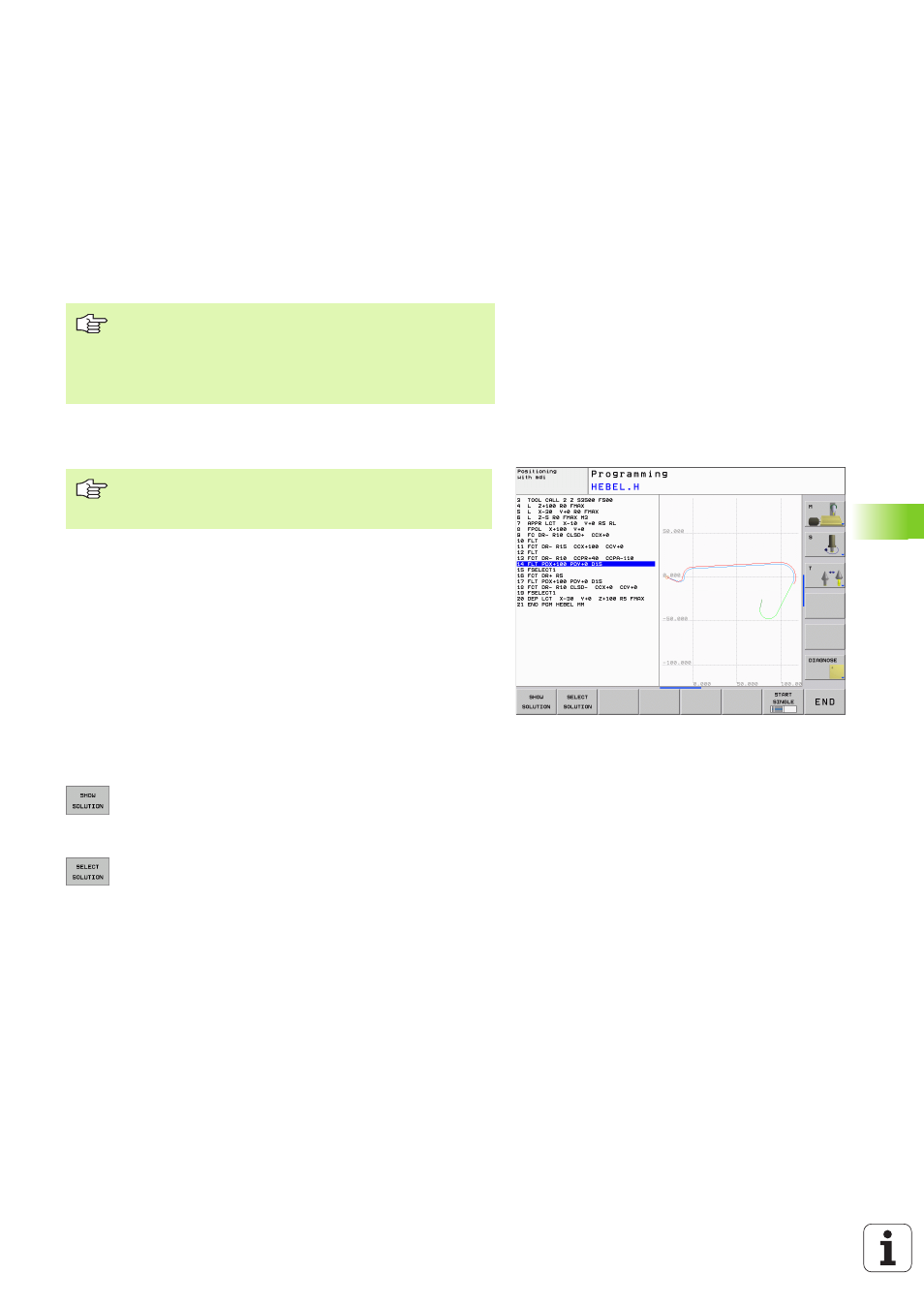
Incomplete coordinate data often are not sufficient to fully define a
workpiece contour. In this case, the TNC indicates the possible
solutions in the FK graphic. You can then select the contour that
matches the drawing. The FK graphic displays the elements of the
workpiece contour in different colors:
If the entered data permit a limited number of possible solutions and
the contour element is displayed in green, select the correct contour
element as follows:
8
Press the SHOW SOLUTION soft key repeatedly until
the correct contour element is displayed. Use the
zoom function (2nd soft-key row) if you cannot
distinguish possible solutions in the standard setting.
8
If the displayed contour element matches the
drawing, select the contour element with SELECT
SOLUTION.
Create FK programs for TNC 4xx:
For a TNC 4xx to be able to read-in FK programs created
on a TNC 320, the individual FK elements within a block
must be in the same sequence as displayed in the soft-key
row.
If you wish to use graphic support during FK
programming, select the PROGRAM + GRAPHICS screen
layout (see “Programming and Editing” on page31).
White
The contour element is fully defined.
Green
The entered data describe a limited number of possible
solutions: select the correct one.
Red
The entered data are not sufficient to determine the
contour element: enter further data.