3 cont our appr oac h and depar tur e – HEIDENHAIN iTNC 530 (340 49x-04) ISO programming User Manual
Page 227
HEIDENHAIN TNC iTNC 530
227
6.3 Cont
our Appr
oac
h
and Depar
tur
e
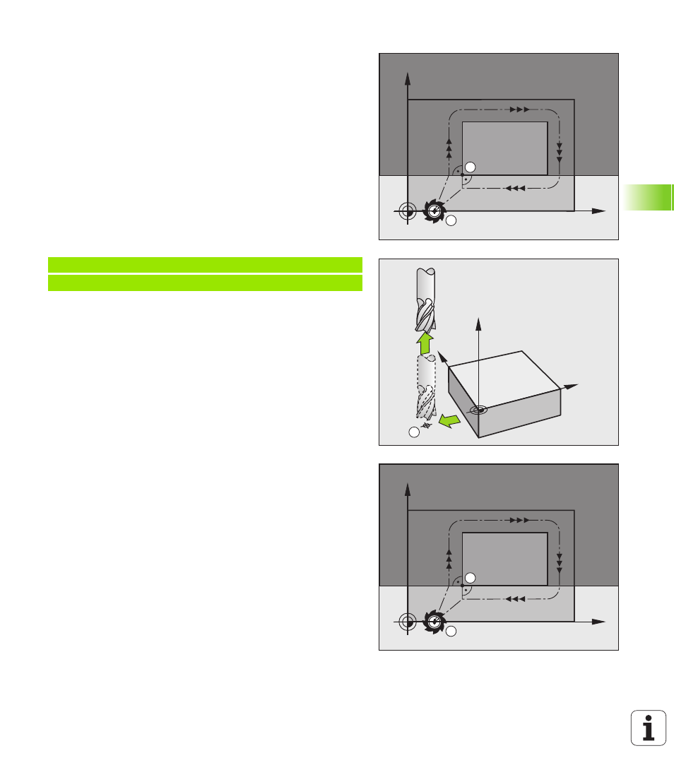
End point
The end point should be selected so that it is:
Approachable without danger of collision.
Near to the last contour point.
In order to make sure the contour will not be damaged, the optimal
ending point should lie on the extended tool path for machining the
last contour element.
Example
Figure at upper right: If you set the ending point in the dark gray area,
the contour will be damaged when the end point is approached.
Depart the end point in the spindle axis:
Program the departure from the end point in the spindle axis
separately. See figure at center right.
Example NC blocks
Common starting and end points
Do not program any radius compensation if the starting point and end
point are the same.
In order to make sure the contour will not be damaged, the optimal
starting point should lie between the extended tool paths for
machining the first and last contour elements.
Example
Figure at upper right: If you set the starting point in the dark gray area,
the contour will be damaged when the first contour element is
approached.
X
Y
A
E
Y
X
Z
E
N50 G00 G40 X+60 Y+70 *
N60 Z+250 *
X
Y
A
E