Defining individual machining positions, Defining a single row – HEIDENHAIN TNC 620 (81760x-01) Cycle programming User Manual
Page 56
Using Fixed Cycles
2.3
PATTERN DEF pattern definition
2
56
TNC 620 | User's Manual Cycle Programming | 3/2014
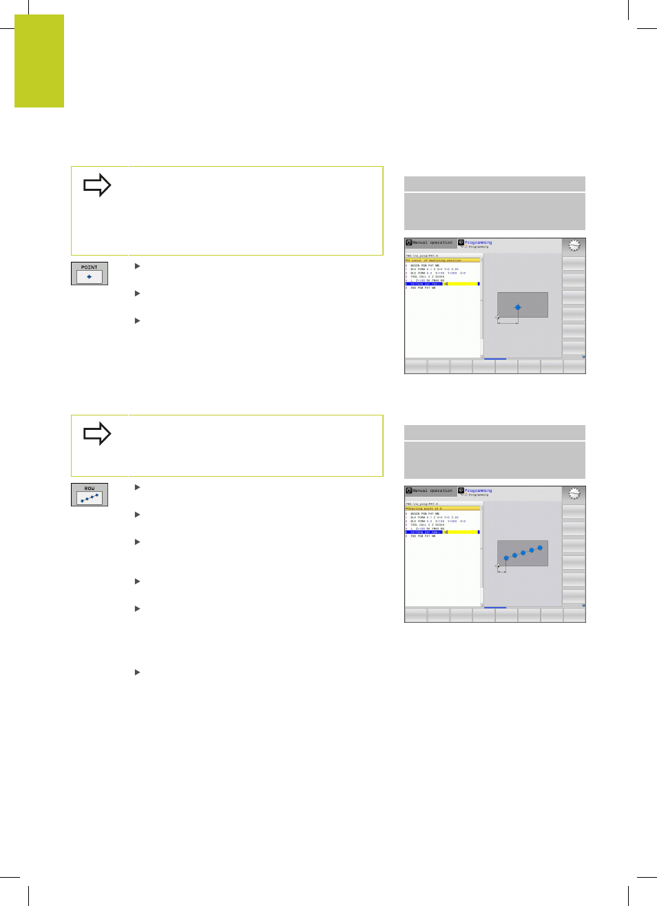
Defining individual machining positions
You can enter up to 9 machining positions. Confirm
each entry with the
ENT key.
If you have defined a
workpiece surface in Z not
equal to 0, then this value is effective in addition to
the workpiece surface
Q203 that you defined in the
machining cycle.
X coord. of machining position (absolute): Enter X
coordinate
Y coord. of machining position (absolute): Enter Y
coordinate
Workpiece surface coordinate (absolute): Enter Z
coordinate at which machining is to begin
NC blocks
10 L Z+100 R0 FMAX
11 PATTERN DEF POS1
(X+25 Y+33.5 Z+0) POS2 (X+50 Y
+75 Z+0)
Defining a single row
If you have defined a
workpiece surface in Z not
equal to 0, then this value is effective in addition to
the workpiece surface
Q203 that you defined in the
machining cycle.
Starting point in X (absolute): Coordinate of the
starting point of the row in the X axis
Starting point in Y (absolute): Coordinate of the
starting point of the row in the Y axis
Spacing of machining positions (incremental):
Distance between the machining positions. You can
enter a positive or negative value
Number of repetitions: Total number of machining
operations
Rot. position of entire pattern (absolute):
Angle of rotation around the entered starting
point. Reference axis: Reference axis of the active
machining plane (e.g. X for tool axis Z). You can
enter a positive or negative value
Workpiece surface coordinate (absolute): Enter Z
coordinate at which machining is to begin
NC blocks
10 L Z+100 R0 FMAX
11 PATTERN DEF ROW1
(X+25 Y+33.5 D+8 NUM5 ROT+0 Z
+0)