Warning – Yaskawa Sigma-5 Large Capacity Users Manual: Design and Maintenance-Rotary Motors-Analog Voltage and Pulse Train Reference User Manual
Page 116
4 Trial Operation
4-10
4.4 Trial Operation with the Servomotor Connected to the Machine
Perform the following steps for trial operation when the servomotor is connected to the machine.
The steps are specified on the condition that trial operation for servomotor without load has been completed in
each control method.
WARNING
• Malfunctions that occur after the servomotor is connected to the machine may not only damage the
machine, but may also cause an accident resulting in death or injury.
Always make sure that the overtravel signals (P-OT and N-OT) are enabled for trial oper-
ation with the servomotor connected to the machine to provide a protective function.
Step
Operation
Reference
1
Turn ON the control power and main circuit power supplies and make the settings for
mechanical configuration related to protective function such as safety function, over-
travel, and brake.
When using the safety function, connect a safety function device to CN8.
Note:
• When not using the safety function, use the SERVOPACK with the safety function
jumper connector (provided as an accessory) inserted into CN8. If the SERVO-
PACK is used without the jumper connector inserted into CN8, no current will
flow to the servomotor and no torque will be output. In this case, "Hbb" will be dis-
played on the panel operator or the digital operator.
• When a servomotor with brake is used, take advance measures to prevent vibration
due to gravity acting on the machine or external forces before checking the brake
operation. Check that both servomotor and brake operations are correct.
5.11 Safety Function
3.3.2 Safety Function Sig-
nal (CN8) Names and
Functions
5.2.3 Overtravel
5.2.4 Holding Brakes
2
Set the necessary parameters for control method used.
5.3 Speed Control
5.4 Position Control
5.5 Torque Control
3
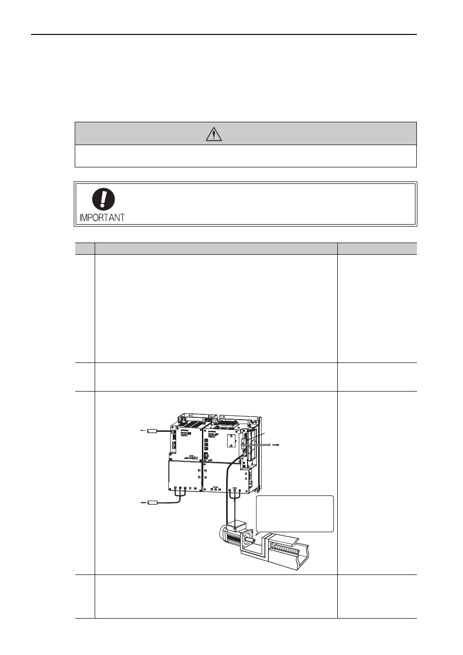
Connect the servomotor to the machine with coupling, etc., while the power is turned
OFF.
−
4
Turn ON the power to the machine (host controller) and then check that the SERVO-
PACK and converter are servo OFF status. Check again that the protective function in
step 1 operates normally.
Note: For steps 4 to 8, take advance measures for emergency stop so that the servo-
motor can stop safely when an error occurs during operation.
5.2.5 Stopping Servomo-
tors after /S-ON Turned
OFF or Alarm Occur-
rence
CN1
To host controller
To main circuit
power supply
To control
power supply
Secure the motor flange to
the machine and connect
the motor shaft to the load
shaft with a coupling or
similar mechanism.