Motherboard layout, Motherboard layout 9, Chapter 3 – Lanner LEC-3100 User Manual
Page 11: Motherboard information
Advertising
9
Motherboard Information
Chapter 3
Embedded and Industrial Computing
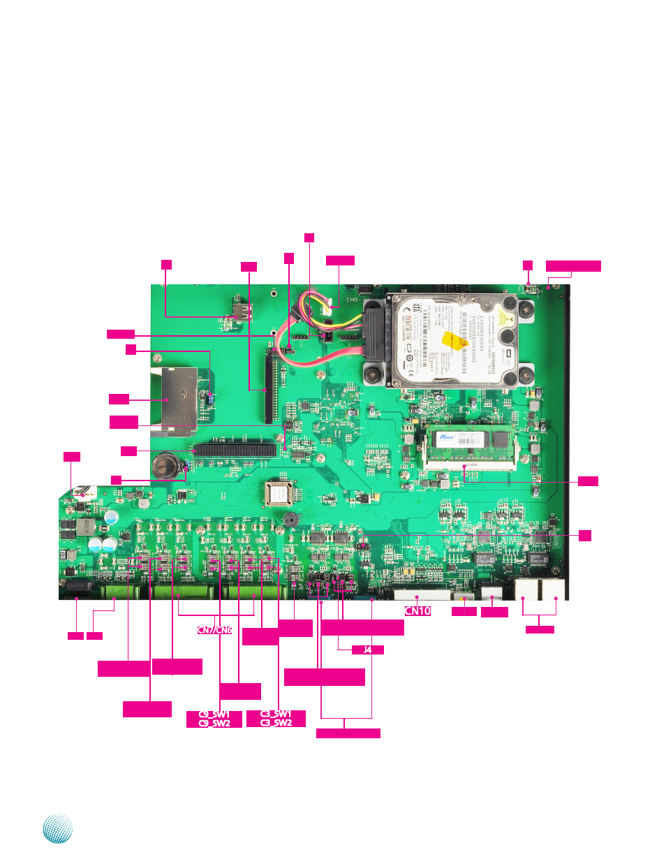
Motherboard Layout
The motherboard layout shows the connectors and
jumpers on the board Refer to the following picture
as a reference of the pin assignments and the internal
connectors
CN1
J5
J11
CN4
J13
USB2
RJ2/RJ1
C10_SW1
C10_SW2
C7_SW1
C7_SW2
C4_SW1
C4_SW2
C6_SW1
C6_SW2
COM2/COM1
J3
SC3T2/SC2T2/SC4T2/
SC1T2
J6
PS1
J7
J8
LCM1
SW1/SW2
CON1
J2
SC3T1/SC2T1/SC4T1/
SC1T1
C8_SW1
C8_SW2
CN8
CN9
C5_SW1
C5_SW2
LAN1
J1
PSW1
Advertising