Front panel features, Front panel features 3, Chapter 1 – Lanner LEC-3100 User Manual
Page 5: Introduction
3
Introduction
Chapter 1
Embedded and Industrial Computing
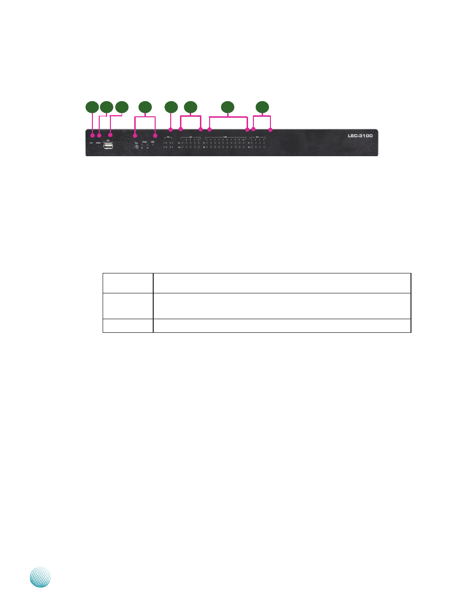
F1 CTR
This is a software reset switch which could be programmed to reset your application to its default settings
F2 Reset Switch
It is a hardware reset switch Use a pointed object to press it 5 seconds then release it to reset the system without
turning off the power
F3 USB 2 0 type A ports
It connects to any USB devices, for example, a flash drive
F5 Run/Power/HDD LED
Run
A programmable dual green/amber LED which can be used for indicating system
status.
Power
Green indicates Power-on, where as Off indicates Power-off status.
P1: Status for the built-in power supply unit
P2: Status for the redundant 1x2-pin Phoenix Contact
Hard Disk
Yellow indicates that HDD is present, whereas Off indicates HDD is not present.
F5 PIO Status LED
The set of 4 LEDs can be programmed to display the status of any hardware components or system operating
status Refer to the Driver and Manual CD for a sample code to implement this feature
F6 LAN Status LED
ACT LED: If the LED is on, it indicates that the port is linked
Link LED: If it blinks, it indicates there is traffic
F7 Serial Port Status LED for COM1 through COM10
The LEDs on the upper row show the status of transmission activities, whereas those on the bottom row show
the status of receiving activities
F8 These LEDs indicate the Digital I/O operating status
The LEDs on the upper row show the connection status of input pins, whereas those on the bottom row show
the connection status of output pins
Front Panel Features
F1
F5
F2
F3
F4
F6
F7
F8