Ordering information, Nt series transceiver development board, Board objects – Linx Technologies MDEV-xxx-NT User Manual
Page 4: Initial setup, Troubleshooting
–
–
–
–
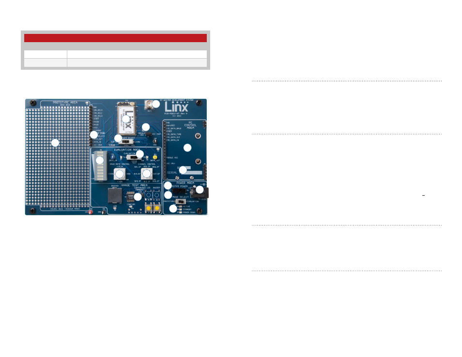
Board Objects
NT Series Transceiver Development Board
1
2
3
4
5
6
7
8
9
10
11
12
13
14
15
17
16
Ordering Information
Ordering Information
Part Number
Description
MDEV-868-NT
868MHz NT Series Master Development System
MDEV-900-NT
900MHz NT Series Master Development System
1. Prototype Area
2. Break-Out Header
3. RSSI Level
4. NT Series Transceiver
5. RP-SMA Antenna Connector
6. Module Power Header
7. Output Power Level
Selection Switch
8. Evaluation Selection Switch
9. Baud Rate Selection Dial
10. Channel (Frequency)
Selection Dial
11. Transcoder Range Test Area
12. PC Control Area
13. 9V Battery (on the back of
the board)
14. DC Power Jack
15. Master Power Switch
16. Mode Selection Switch
17. Module Mode Indicator LEDs
Figure 2: Ordering Information
Figure 3: NT Series Transceiver Development Board
2
3
Initial Setup
Unpack the development system, attach the antennas and install a 9V
battery on each development board. The boards can be used in two
different configurations: Prototype and Evaluation. The Mode Selection
switch sets the configuration. By default, the boards are set to Range Test
in the Evaluation configuration.
Evaluation Configuration
Setting the Mode Select switch to the EVALUATION (right) position enables
the Evaluation Configuration. In this configuration, the module’s signal lines
are routed to the Evaluation Area for control. This enables the module to be
configured by the controls on the board while allowing custom data to be
sent over the link.
Range Test
The development boards feature an onboard Linx MT Series transcoder
which facilitates range testing. Buttons on one board activate a light or
buzzer on the other. A confirmation LED provides visual acknowledgment
that a transmission was received across the wireless link.
Range Test is part of the Evaluation configuration and is the default
configuration out of the box. To use the boards this way, place the Mode
Select switch to Evaluation and the Evaluation Select switch to the RANGE
TEST (middle) position. This routes the DATA_IN, DATA_OUT and T/R_SEL
lines to the MT Series Transcoder.
Prototype Configuration
Setting the Mode Select switch to the PROTOTYPE (left) position enables
the Prototype Configuration. In the Prototype configuration, the module’s
signal lines are routed to the break-out header next to the Prototype Area.
This allows the module to be controlled with custom application circuitry.
Software Development
The kit includes one USB interface board for connection to a PC. Included
software demonstrates use of the module’s Command Data Interface (CDI).
Troubleshooting
If the boards fail to work out of the box, then try the following:
• Make sure that the Master Power, Mode Select and Evaluation Select
switches are in the correct positions. The Active LED should be on