The power area, The evaluation area – Linx Technologies MDEV-xxx-NT User Manual
Page 6
–
–
–
–
6
The Power Area
The Power Area has two switches that control power to the board and the
type of operation (Figure 7). The Master Power switch supplies power from
the 9V battery or the power jack to the board. The power jack accepts a
2.5mm plug with the tip ground and the shell 7 to 12VDC.
The Mode Select switch configures the board for either Prototype operation
(left position) or Evaluation operation (right position). In Prototype operation,
the module’s signal lines are routed to the header next to the Prototype
Area. This allows custom circuits to easily interface with the module.
In Evaluation operation, the module’s signal lines are routed to the
Evaluation Area. The controls in this area allow the module to be operated
without any other circuits, microcontrollers or a PC.
Three LEDs show the state of the module. Active shows the module is
on and ready for operation. Standby and Power Down indicate that the
low power modes have been entered and the module is not ready for
operation.
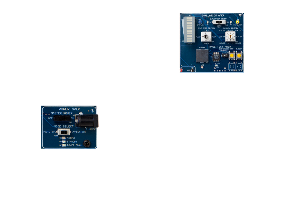
The Evaluation Area
The Evaluation Area is activated by setting the Mode Select switch to the
right position. Figure 8 shows the Evaluation Area.
The Evaluation Select switch configures the area for different types of
evaluation. The left position puts the module into transmit mode.
The orange TX LED lights up and any data present on the blue DATA_IN
test point is transmitted by the module.
Figure 7: The Development Board Power Area
7
The right position puts the module into receive mode. The yellow RX LED
lights up and data received by the module is output on the yellow
DATA_OUT test point.
These two configurations allow the module to transmit and receive custom
data while controlling the baud band and channel with the frequency dials
on the board. It is similar to the Prototype Area, but requires less external
circuitry to configure the module. The switches on the board are used for
hardware configuration in this mode.
The Baud Rate Control dial sets the BAUD0 and BAUD1 lines to configure
the module’s baud band. This should be set the same on both boards for
proper operation.
The Channel Control dial sets the CHAN_SEL0, CHAN_SEL1 and
CHAN_SEL2 lines to configure the module’s channel. This should be set
the same on both boards for proper operation.
An LED bar is used to provide a general indication of the RF signal
strength. The closer the active LED is to the top, the stronger the received
signal level. The receiver must be active for at least one second for the
RSSI level to update.
The center position on the Evaluation Select switch activates the Range
Test Area, allowing the link’s range to be evaluated. This area is described
in detail in the Range Test Area section of this user’s guide.
Figure 8: The Development Board Level Adjust Section