The pc software – Linx Technologies MDEV-xxx-NT User Manual
Page 8
–
–
–
–
The three position slide switch (2) controls the CMD_DATA_TYPE line. This
line tells the module that the data coming in on the CDI is either command
data for configuring the module (middle position) or packet data to be
transmitted over the air (top position). The bottom position connects this
line to the DTR line on the USB or RS-232 interface. This allows the PC
software to control the line, giving it the ability to configure the module and
send data.
Test points for CMD_DATA_IN (3) and CMD_DATA_OUT (4) are provided so
that the communications can be monitored.
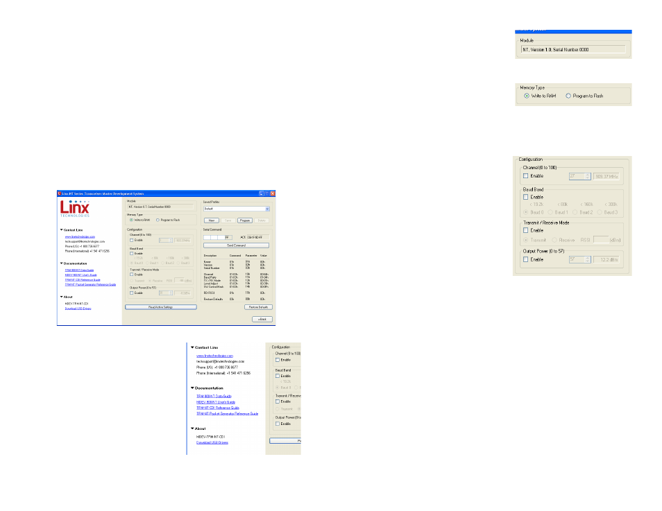
The PC Software
The kit includes PC software that can be used to configure the module
through the PC interface daughter board. Figure 11 shows the software.
The left side of the window contains
labels that expand to show links to useful
information (Figure 12). This includes the
Linx Technologies contact information
and links to the website for the latest
product documentation and software
updates. Clicking on these links opens
the page in the computer’s default web
browser.
Figure 11: Development Kit PC Software
The command portion of the window
starts in the middle of the window (Figure
13). At the top is a box that states the
product name, firmware version and
serial number.
Below this is a selection that determines
how the module is configured (Figure 14).
Writing to RAM is faster, but the settings
are lost when power is cycled to the module. Programming to flash takes a
bit longer (5ms/byte), but the settings are retained when power is cycled to
the module.
Below this are the configuration settings
(Figure 15). These allow the software to
change the channel, baud band, transmit
and receive mode and the output
power. By default the module looks to
its hardware pins for these configuration
settings, so software control must be
enabled for it to take control. This is
done by checking the Enable checkbox
in each section.
The Channel configuration allows the
user to select from among all 101 channels offered by the module rather
than just the eight available with the hardware lines. A selection box shows
the channel and a text box shows the channel’s frequency.
The Baud Band setting adjusts internal filters and other settings to set
the transceiver’s maximum over-the-air data rate. The Baud Band section
allows for the selection from among the four baud bands.
The Transmit/Receive Mode selection activates the transceiver’s transmitter
or receiver. When the receiver is active the measured RSSI level is shown in
the text box.
The Output Power section allows the module’s transmitter output power
level to be adjusted. The NT Series has 57 power levels that drop the
power in approximately 0.5dB increments. The adjacent text box shows
the approximate power. This is not a measured value, but an approximate
value based on characterization of the modules.
Figure 12: Development Kit PC Software
11
10
Figure 13: Development Kit PC Software
Figure 14: Development Kit PC Software
Figure 15: Development Kit PC Software