The prototyping area, The tx power select switch, The transceiver area – Linx Technologies MDEV-xxx-NT User Manual
Page 5
–
–
–
–
• Make sure that the Baud Rate and Channel switches are set the same
on both boards
• Check that the antennas are connected
• Make sure that a jumper is installed on the Module Power Header
• Make sure that the batteries are not dead
If all of these appear to be in order, please call +1 800 736 6677 or e-mail
[email protected] for technical support.
The Prototyping Area
In addition to its evaluation functions, the board may also be used for
product development. It features a prototyping area to facilitate the addition
of application-specific circuitry (Figure 4). The prototyping area contains a
large area of plated through-holes so that external circuitry can be placed
on the board. The holes are set at 0.100" on center with a 0.040" diameter,
accommodating most industry-standard SIP and DIP packages.
External circuitry can be easily interfaced to the NT transceiver through the
breakout header (TS1) to the right of the prototyping area. The Mode Select
switch should be set to the left position to enable the module’s lines to
be controlled from the prototyping area. At the bottom of the prototyping
area is a row connected to the 5V power supply and at the top is a row
connected to ground.
Note:
The onboard 5-volt regulator has approximately 600mA available
for additional circuitry. If more current is required, the user must add an
additional regulator or power the board from an external supply.
Figure 4: The Development Board
Prototyping Area
4
5
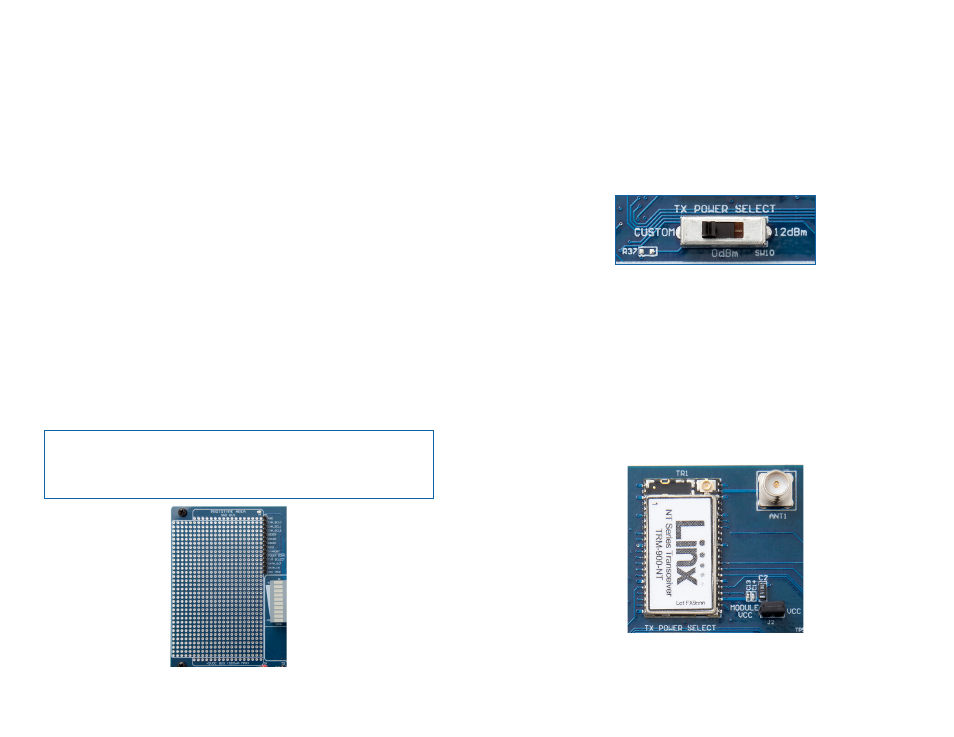
The TX Power Select Switch
The board has a switch to select among three different transmitter output
power levels (Figure 5). The right position sets the module to full power of
about 12dBm. The center position sets the output power to about 0dBm,
which is the legal limit for most applications. The left position uses resistor
R37 to set the power. This position is an unpopulated 0603 size resistor
location. A resistor can be placed here to set the output power to any
available level. Please see the NT Series Data Guide for more information
on resistor values. A power cycle is required for changes to take effect.
The Transceiver Area
The transceiver section consists of the transceiver module and a reverse-
polarity SMA connector as shown in Figure 6. The RP-SMA connector
is FCC compliant and reverses the center pin and socket. RP-SMA
connectors will mate with but not provide electrical connection to standard
SMA connectors or SMA equipped antennas. A header next to the module
disconnects the module’s power from the main board power. This can
be used for current measurements or to power the module alone from an
external power source. A jumper must be installed to power the module
from the board.
Figure 5: The Development Board TX Power Select Switch
Figure 6: The Development Board Transceiver Area