The range test area, The pc control area – Linx Technologies MDEV-xxx-NT User Manual
Page 7
–
–
–
–
To achieve maximum range, keep objects such as your hand away
from the antennas and ensure that the antennas on the boards have
an unobstructed line-of-sight path to each other. Range performance is
determined by many interdependent factors. If the range you are able to
achieve is significantly less than specified by Linx for the products you are
testing, then there is likely a problem with either the board or the ambient
RF environment in which the board is operating. First, check the battery,
switch positions, TX output power setting and antenna connection.
Check the range performance on different channels. Next, measure the
receiver’s RSSI voltage with the transmitter turned off to determine if
ambient interference is present. If this fails to resolve the issue, please
contact Linx technical support.
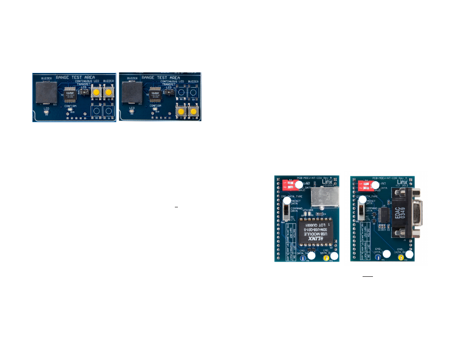
The PC Control Area
The PC Control Area is used with a daughter board to connect the
module’s Command Data Interface to a PC. This advanced feature is a
serial data interface for configuration and data transfer. One USB interface
board is included with the development kit. Additional USB interface boards
or an RS-232 interface board can be purchased separately.
The top DIP switch (1) controls the TRPT/PKT line on the module. This
line selects between transparent data transmission and packet data
transmission. Slide it to the left for transparent data and to the right for
packet data.
The bottom DIP switch (1) controls the CMD_DATA_BAUD line on
the module. This is the data rate for the CDI and has no effect on the
over-the-air data rate. Slide to the left for 57,600bps and to the right for
9,600bps.
8
The Range Test Area
The board features an MT Series remote control transcoder with two push
buttons, a buzzer and an LED. The two boards in the kit are populated
differently so that the button inputs on one board are outputs on the other
board. Figure 9 shows the differences.
When a button is pressed on one board, the status of both buttons is
captured, encoded into a data stream, and transmitted. The data
recovered by the receiving board is decoded and the transcoder’s data
lines are set to replicate the states of the buttons, driving either the buzzer
or the LED. A confirmation packet is then sent to the transmitting board
activating the Confirm LED.
To activate this area of the board, the module’s DATA and T/R_SEL lines
must be routed to the transcoder. This is accomplished by setting the
Mode Select switch to the right position and the Evaluation Select switch to
the middle position.
After the boards have been configured, place Board A on a flat surface
and turn it on. Turn on Board B and press button S1. The buzzer on Board
A will sound and the Confirm LED on Board B will light up. The usable
range of the link in your environment can be ascertained by carrying Board
B away from Board A. Switch SW11 has been provided to continuously
transmit the LED activation without having to hold down a button.
As you near the maximum range of the link in your area, it is common for
the signal to cut in and out as you move. This is normal and can result from
other interfering sources or fluctuating signal levels due to multipath effects.
The areas in which this occurs are commonly called “nulls” and simply
walking a little farther will often restore the signal.
Figure 9: The Development Board Range Test Section
Board A
Board B
9
Figure 10: PC Interface Boards
1
2
3
4
1
3
4
2