Using the boards as a design reference, About antennas – Linx Technologies MDEV-xxx-NT User Manual
Page 9
–
–
–
–
12
The “Read Active Settings” button
at the bottom (Figure 16) reads the
existing configuration settings from the
module and adjusts the values in the
configuration sections based on the
module’s current configuration.
The right column in the window starts
with the Profile section (Figure 17).
Specific configuration settings can be
saved as a profile and loaded into a
connected module. This allows the
software to be used in small-scale
production lines for products that provide
connection to the CDI.
Select the “New” button to create a new profile and give it a name. Set
the configuration controls as desired and click the “Save” button to save
the profile. Click the “Program” button to send the profile to the module.
All of the profiles saved on the PC can be viewed in the drop down menu
and sent to the module with the “Program” button. The “Delete” button
removes the selected profile from the computer.
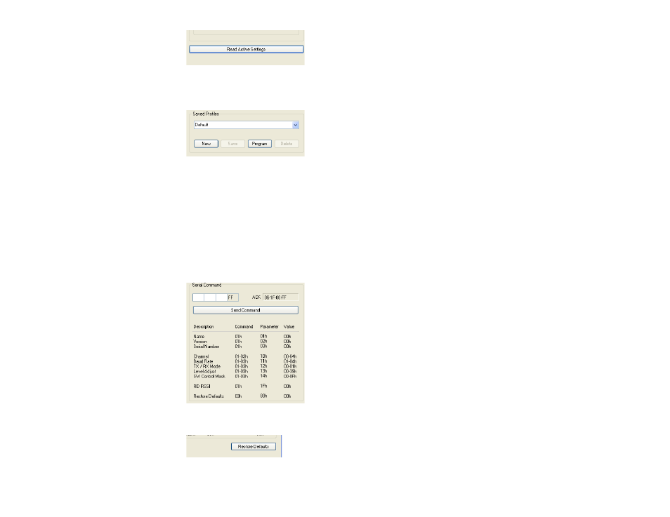
The Serial Command section (Figure 18)
provides the ability to send a specific
packet to the module. Byte values are
typed into the boxes to create the packet
and the “Send Command” button sends
the packet to the module. The ACK text
box displays the module’s response. The
possible values for each byte are shown
in the table below the “Send Command”
button.
The “Restore Defaults” button (Figure 19)
writes the factory default values to the
transceiver. This is an easy way to restore
the module to a known configuration.
13
Figure 16: Development Kit PC Software
Figure 17: Development Kit PC Software
Figure 18: Development Kit PC Software
Figure 19: Development Kit PC Software
Using the Boards as a Design Reference
From a layout perspective, the master development boards included in this
kit are quite simple, yet they illustrate some important techniques that can
be incorporated into a design. The module’s mounting pads extend slightly
past the edge of the part. This eases hand assembly and allows for better
heat conduction under the part if rework is necessary. The use of a full
ground plane fill on the lower side of the board serves three important
purposes.
First, since a ¼-wave antenna is employed, the ground plane is critical to
serve as a counterpoise. Application Note AN-00500 and AN-00501
provide additional details on how a ground plane affects antenna function.
Second, a ground plane suppresses the transfer of noise between stages
of a product as well as unintentional radiation of noise into free space.
Third, a ground plane allows for the implementation of a microstrip feed
to the antenna. The term microstrip refers to a PCB trace running over
a ground plane that is designed to serve as a 50-ohm transmission line
between the module and the antenna. A microstrip is implemented on this
evaluation board. The module’s data guide and a calculator available on the
Linx Technologies website provide more information on the microstrip
implementation and calculations.
About Antennas
The choice of antennas is one of the most critical and often overlooked
design considerations. The range, performance and legality of an RF link
are critically dependent upon the type of antenna employed. Linx offers a
variety of antenna styles that may be considered for a design. Included with
the development system is a Linx CW Series connectorized whip antenna
that should be connected prior to using the kit. Despite the fact that the
antenna is not centered on the board’s ground plane, it exhibits a VSWR of
<1.7 and demonstrates the module’s best practical performance.