Mount tamperproof magnet here – Sealey SWSKIT User Manual
Page 3
Sound output: Chime (ding-dong)
Smart Panel – flashes GREEN every 1.5 seconds with triggered
zone indicated (To stop panel flashes - press )
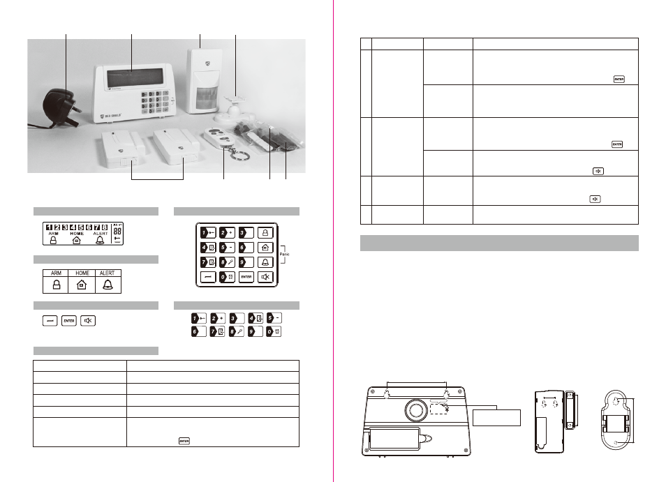
1.4 Introduction to the Smart Panel
1.5 Introduction to the Smart Panel sound alert and backlight
LCD Screen:
Function Buttons:
Programming Buttons:
Numeric Buttons:
Keypad:
Other:
9V DC INPUT port
Siren output
Battery compartment:
4 x Pin header, 4 x Jumper
8 x Pin header, 1 x Jumper
“RESET” button
For AC/DC adaptor
120dB
For 9V Al
kaline back-up battery
For House Security Code setting
For Zone Code setting
If you forget the 4-digit PIN, press the “RESET” button located
in the battery compartment and enter factory default PIN “ 1 2
3 4 ” followed by to restore factory settings.
Operating Mode
ARM
Situation
Zone triggered
under ARM status
Alarm duration: Adjustable between 1 – 6 minutes (siren).
Default is 1 minute
Smart Panel - flashes RED every 1.5 seconds with triggered
zone indicated (To stop - enter 4-digit PIN and press )
Sound alert and backlight indication
1
Alarm set under
ARM status
No siren
Smart Panel - flashes RED every 5 seconds providing an
intruder deterrent (different from when an intrusion occurs and
the panel rapidly and continuously flashes RED).
Alarm duration: Adjustable between 1 – 6 minutes (siren).
Default is 1 minute
Smart Panel - flashes RED every 1.5 seconds with triggered
zone indicated (To stop - enter 4-digit PIN and press )
HOME
Zone triggered
under ARM status
2
Zone triggered
under ALERT
status
Sound output: Chime (ding-dong)
Smart Panel – flashes GREEN every 1.5 seconds with triggered
zone indicated (To stop panel flashes press )
ALERT
Zone triggered
under ALERT
status
3
Smart Panel – YELLOW backlight remains ON for 10 seconds
after entering into STANDBY mode
STANDBY
Silent
4
SECTION 2 – INSTALLING THE WIRE-FREE HOME PROTECTION SYSTEM
2.1 Installing the Smart Panel
WARNING: The Smart Panel has a built-in tamper-proof switch to prevent the system being
disabled by an intruder. When fixing the Smart Panel to a wall, first ensure that it is in Standby mode to avoid
the alarm sounding.
2.1.1 Locating the Smart Panel and tamperproof switch
Determine the location of the Smart Panel, which should be placed:
- within a few feet of an electrical outlet
- where it is easily accessible
- away from doors or windows that could be accessed by intruders
- way from extreme temperature sources (radiators, ovens, stoves etc.) and large metal objects that could
interfere with the wireless performance
2.1.2 Wall mounting the Smart Panel and tamperproof switch
• First cut out the mounting template for the Smart Panel along with the area which is marked out for the
position of the tamperproof magnet (see below).
A
D
H
B
C
E
G
F
Mount tamperproof magnet here
84mm
62mm
43mm
16mm
Area for positioning
tamperproof magnet
- 3 -
- 2 -