Smps - installation guide 5, Figure 1: smps – general view – RISCO Group SMPS 3A User Manual
Page 5
Advertising
SMPS - Installation Guide
5
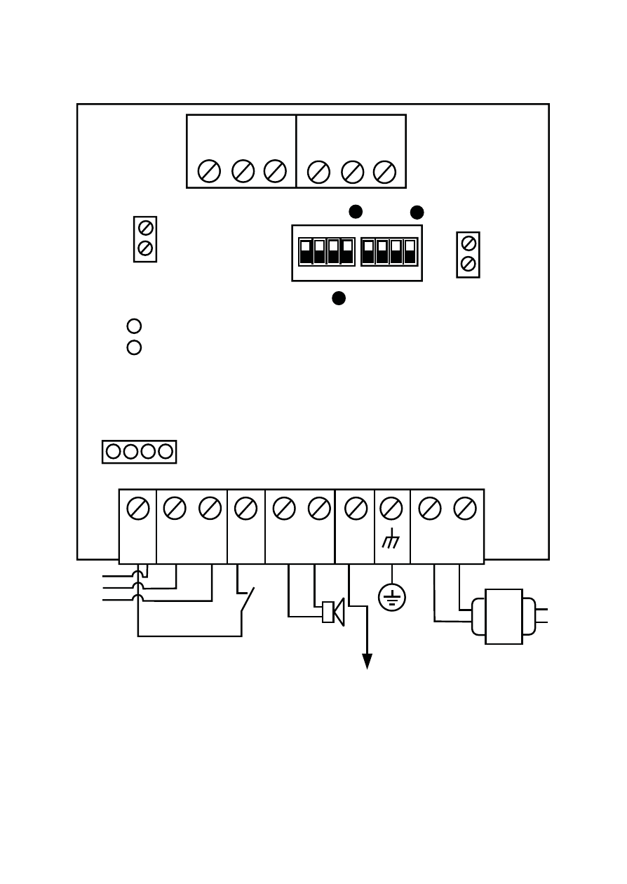
The SMPS components and jumpers are shown in Figure 1:
(PS LED)
(UO LED)
AC
AUX
RED
BELL LS
+ -
TAMP
BUS
YEL GRN
COM
BLK
BUS
BELL/LS
(Bell/Loudspeaker
Jumper)
OC
(Over Current LED)
BAT
(Battery Jumper)
PS
Battery
Connections
Loudspeaker/
Bell
Power to accessories
And detectors
Transformer
1 2 3 4
1 2 3 4
ON
N.O
N.C
C
UO
1
C
UO
2
N.O
N.C
UO
Figure 1: SMPS – General View
Advertising