RISCO Group SMPS 3A User Manual
Page 7
SMPS - Installation Guide
7
3. When attaching the box to the wall, it is recommended to use Ø4.2mm,
32mm length screws (DIN 7981 4.2X32 ZP)
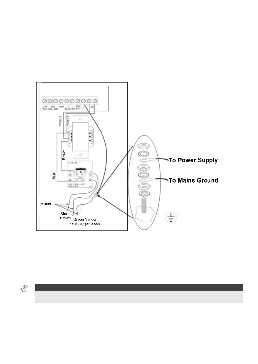
4. Connect the incoming mains cable to the main fuse terminal block as
shown in Figure 3.
5. Wire the SMPS terminals as described in “Power Supply Terminal Wiring”
on pages 8 - 9.
Figure 3: SMPS – AC & Ground Connection
6. Set the SMPS jumpers and the dipswitches as described in “DIP Switches
Settings” on page 11 and section on page 11.
7. Locate the battery at the bottom of the SMPS box.
8. Connect flying leads (battery connectors) from the SMPS board to the
battery terminals - (+) Red, (-) Black).
NOTE:
Use only Lead Acid battery type, rated 12V, 7-21AH (maximum) and safety approved in
accordance with the national standards!
9. Switch on the Mains.
10. Perform a BUS test using the ProSYS menu (refer to ProSYS Installation
and Programming Manual).