RISCO Group SMPS 3A User Manual
Page 8
8
SMPS - Installation Guide
11. Perform a diagnostic test of the SMPS output and battery, using the
ProSYS software as described in the User Programming Menu section on
page 13.
12. Close the SMPS metal box.
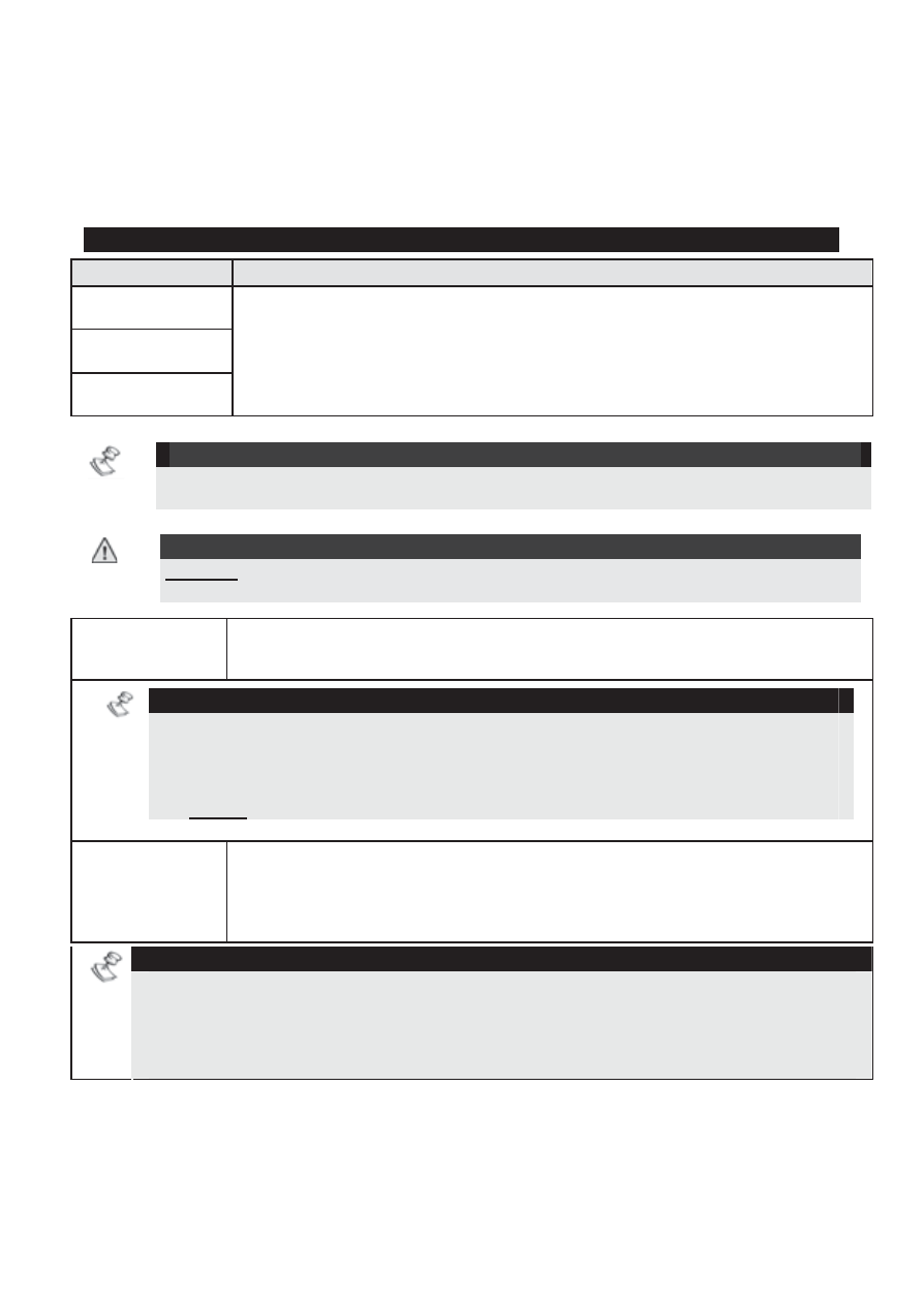
Power Supply Terminal Wiring
Terminal
Description/Action
COM BLK
BUS YEL
BUS GRN
BUS terminals: used to connect the SMPS and its Utility
Output module to the ProSYS communication Bus. Connect
the wires respectively, point to point, according to the indicated
colors.
NOTE:
Maximum permitted wire run for Bus wiring from the SMPS to the ProSYS is 300m
(1000 ft)!
IMPORTANT
:
DO NOT connect the AUX (RED) terminal to the ProSYS BUS. Ensure that the
incoming AUX (usually red) wire from the ProSYS Bus is disconnected!
TAMP
Used for connection of the box’s tamper switch between the
TAMP and the COM terminals (normally closed).
NOTES:
1. It is not necessary to use the box tamper if another module sharing the same
box is equipped with one.
2. To avoid Tamper trouble, if NO connection is made for the TAMP terminal,
connect a wire between the TAMP and COM terminals.
3. Do not use an End of Line resistor in the tamper switch circuit!
BELL
Used to connect an external sounder driven by the SMPS (bell
or loudspeaker). Position the Bell/LS jumper respectively for the
connected device as described in the Jumper Settings section
on page 11.
NOTES:
1. To avoid bell loop trouble, if NO connection is made for the BELL/LS
terminals, connect a 2.2K
ȍ resistor in its place.
2. Use a larger wire gauge if the distance between the sounder and the SMPS is
significant. Take the sounder(s) current draw into account when selecting a wire
gauge (see About Wires on Page 17).