Retrotec USACE User Manual
Page 385
Appendix J J9
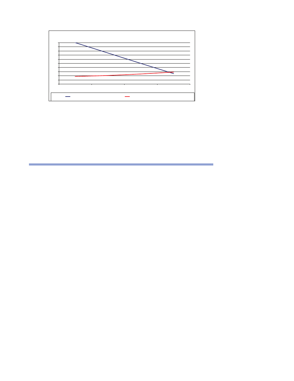
Figure J8. High Effi ciency Dehumidifi cation System: Energy Savings Vs. Design Air Flow @ 25%
reheat to 65F/68F – Typical for facilities that need minimal reheat.
High Efficiency Dehumidification System Energy Savings @ 25% Reheat to 65F/68F
0%
10%
20%
30%
40%
50%
60%
70%
80%
90%
100%
1
2
3
4
Percent of Design Airflow
Percentage of Cooling and Reheat Energy Saved
J.6 Install a Continuous Commissioning, Monitoring and
Verifi cation System to Maintain Savings Persistence of
the Chiller Plant and HVAC Systems
Essentially, this consists of installing accurate temperature sensors on the inlet
and outlet of each chiller and heat recovery unit evaporator and condenser;
installing an accurate low-range differential pressure transducer across the
evaporator of each chiller and heat recovery chiller and using the differential
pressure to calculate the fl ow rate through the chiller; installing a kW trans-
ducer on each chiller; and installing kW transducers on each pump and cool-
ing tower fan and air distribution fan, or, if they are powered by variable fre-
quency drives, obtaining the kW from the VFD over an RS 485 or other net-
work connection. Air handlers that are equipped with economizers must also
be equipped with return air and mixed air temperature sensors and accurate
supply air temperature sensors. If there is budget available, large AHUs should
have DP transducers installed across the coils, as well as and inlet and outlet
water temperature sensors so that tonnage at the AHUs can be calculated as
well. Software would then be implemented to calculate the effi ciency of each
piece of equipment, and then trends and alarms would be set up so that there
would be a historical database of equipment and system performance. The
alarms would be triggered when the system or equipment started operating
outside the boundaries set during system startup.