Retrotec USACE User Manual
Page 176
D46 ENERGY & PROCESS ASSESSMENT PROTOCOL
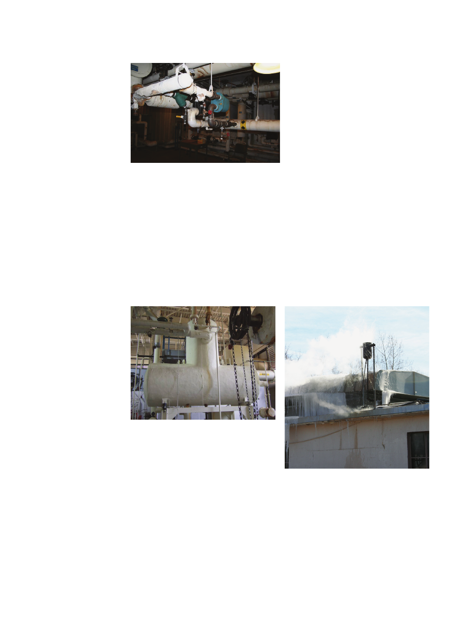
D.4.1.4 Leaking Steam Traps (Waste)
Figure D72. Steam trap downstream of heat
exchanger that requires periodic checking for
proper operation.
A steam trap (Figure D72) is a device that allows condensed steam to pass but
stops steam fl ow. Over time, the internal parts will fail, which can result in the
trap failing in either the closed or open position. If it fails closed, then steam
will not fl ow to the heating device, and it will stop heating. If the trap fails in
the open position, the heating device will continue to function, but additional
steam will be lost through the trap opening or orifi ce. The trap orifi ce size can
be obtained from the trap manufacturer. They typically range in diameter from
0.8 to 12.5 mm (1/32 to ½ in). A leak through a 1/8-in orifi ce is equal to almost
0.015 Btu/min (15 pounds/hr) in a 206.8 kPa (30 psig) system.
D.4.1.5 Overventing the Deaerator (Ineffi ciency)
Figure D73. Heating plant deaerator.
Figure D74. Overventing of deaerator resulting
in ice on heating plant roof.
The function of the deaerator (Figure D73) is to heat up the boiler feed water
to remove dissolved gases such as air—and, especially, oxygen and carbon di-
oxide. Air in the boiler can inhibit heat transfer. The presence of oxygen and
carbon dioxide causes destruction of the piping system, leading to premature
failure. The water in the deaerator is heated to approximately 104.4 °C (220 °F)
in a pressurized tank. This tank is vented to allow the removal of the dissolved
gases. If more venting is done than is required, energy used to create the es-
caping steam is wasted (Figure D74).