Rose Electronics CrystalView DVI Mini User Manual
Page 19
CrystalView DVI Mini Installation and Operations Manual
15
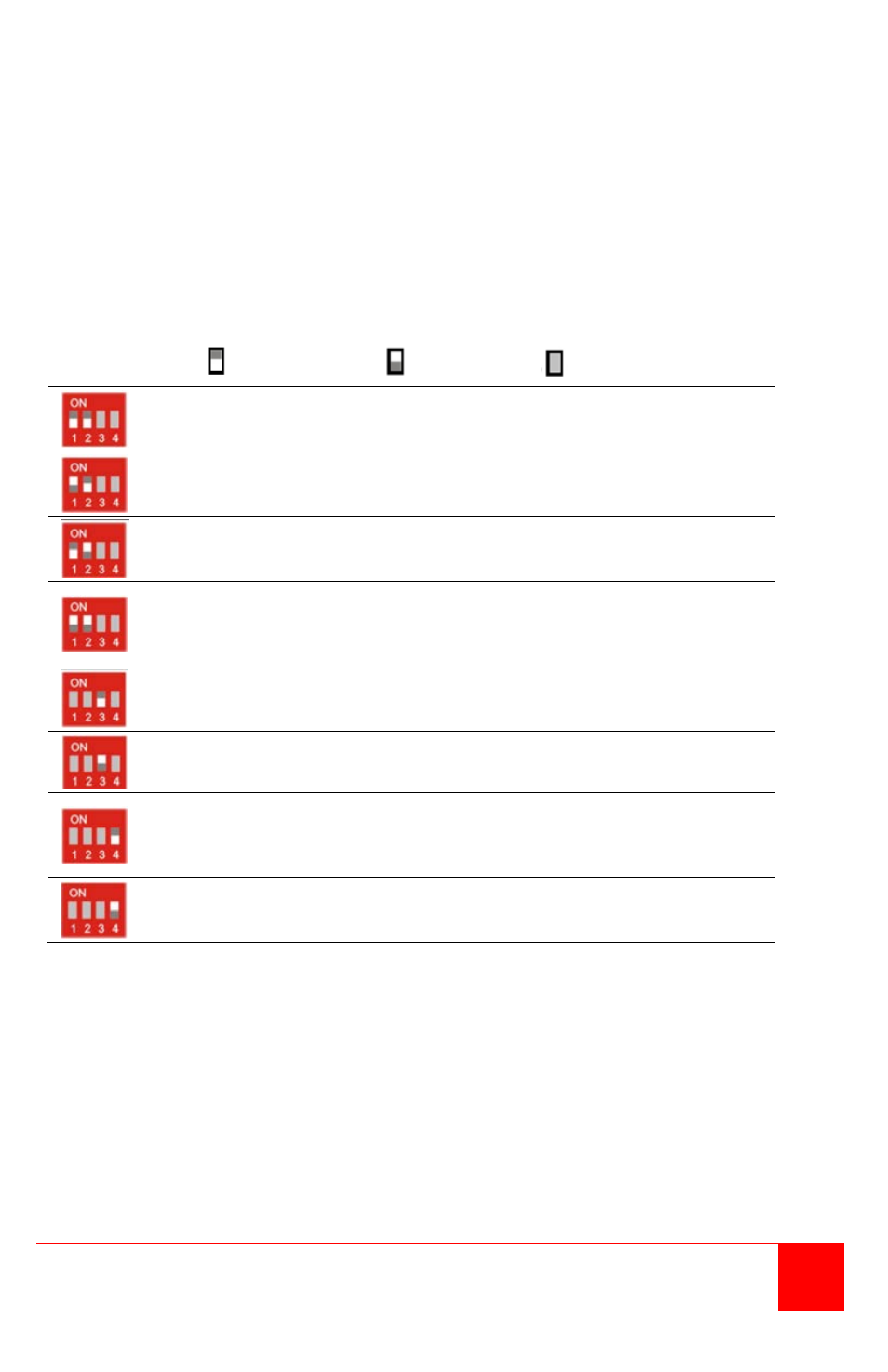
Receiver Dip-switch settings
The receiver Dip-switches are used to adjust the CATx cable length. The
installation cable should be Type AWG24. Patch cables or flexible CATx cables
(AWG26/7) may be used but this reduces the cable distance by approximately
50%. Keep this in mind when adding flexible cabling.
The default switch setting is preset for automatic adjustment. This setting is
acceptable for most configurations. The default setting should only be changed
if the CATx cable length is short or the image quality is not satisfactory.
DIP Switch
Position
Function
= Switch down
= Switch up
= Switch not used
Automatic cable length adjustment (Default setting)
Cable length greater than 33 ft. (10 m)
Cable length greater than 66 ft. (20 m)
Max. cable length: use this setting if exceeding the max
recommended cable length or if the video quality is not
acceptable using the automatic adjustment setting.
Inhibits reading of the DDC information from the
attached monitor
Allows reading of the DDC information from the
attached monitor
Standard Operation mode: Standard operation (Default)
Dip-Switch 4 must be in the “OFF” (down) position
during normal operation
Test operation mode: Firmware update
Set only during Firmware Update, if required
Figure 10. Receiver Dip switch settings
CATx cables should have ferrites on both ends of the cable close to the
transmitter and receiver’s RJ45 connector.
A point to point connection is required.
Patch panels in the line are allowed