Figure g, Blower air adjustment, Figure h – Thermo Pride Air Handlers ECM Blower 13/14 SEER (AH2) User Manual
Page 11
Advertising
9
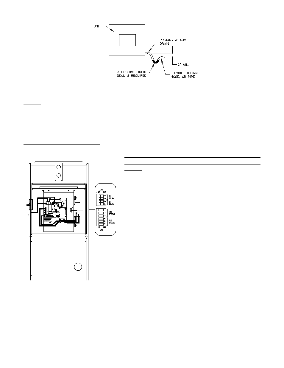
Figure G
NOTE: Drain lines must be pitched no less than 1/4" per foot away from the air handler.
BLOWER AIR ADJUSTMENT
The ECM blower control must be set in order to
establish proper air movement. Use the following steps to
do this:
1. Identify to tonnage of the condensing unit that will be
used.
2. If Hydronic heat is to be used, identify your BTU heat
requirements, preferred supply air temperature, water
temperature and water flow through the coil in gallons per
minute.
3. Locate the blower control board mounted to the front of
the blower assembly.
4. Locate the red switch block labeled SW1 for adjusting the
Heating and Cooling blower speed.
5. Locate SW2, just below SW1, for adjusting Blower
delays.
Figure H
Advertising
This manual is related to the following products: