Blower time delay, Duct system, Table d1: delays before blower cycles “on or “off – Thermo Pride Air Handlers ECM Blower 13/14 SEER (AH2) User Manual
Page 15
13
BLOWER TIME DELAY
In cases where the yellow wires are used to start and stop the hydronic pump, SW2 may be used to delay
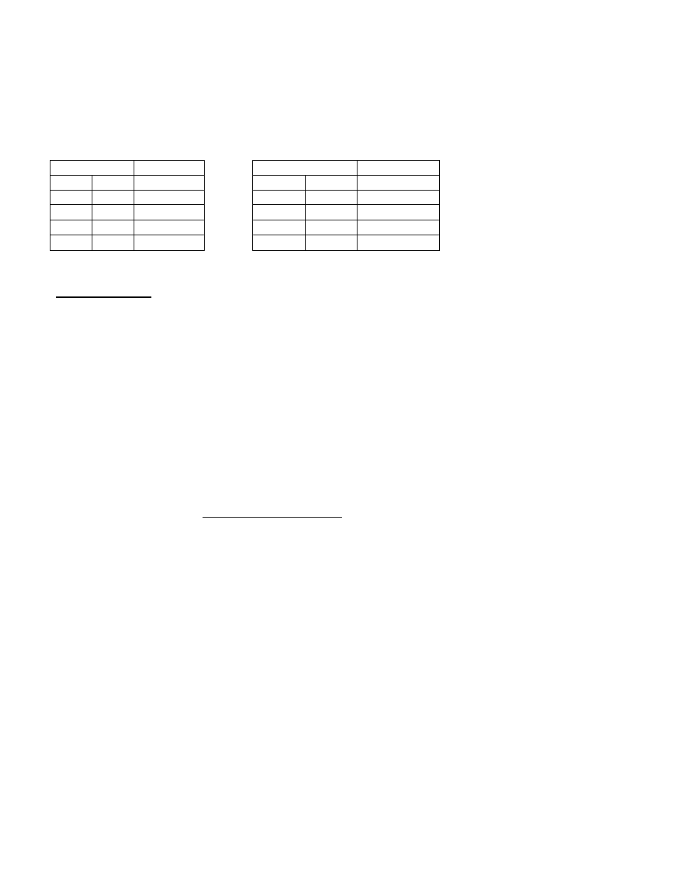
when the blower is cycled on or off to increase comfort and efficiency.
Use Table D1 to set the switches appropriately
Table D1: Delays before blower cycles “ON or “OFF”
SW2 Positions
“ON” Delay
SW2 Positions
“OFF” Delay
1
2
(Seconds)
3
4
(Minutes)
OFF
OFF
30
OFF
OFF
2
ON
OFF
60
ON
OFF
4
OFF
ON
120
OFF
ON
6
ON
ON
480
ON
ON
8
DUCT SYSTEM
The duct system and load sizing calculation should follow the design standards of Air Conditioning
Contractors of America (ACCA) - manuals D & J - or the American Society of Heating, Refrigeration and
Air Conditioning Engineers, Inc. (ASHRAE) Latest Edition Fundamentals Volume.
To aid you in evaluating existing duct systems quickly, review the chart on Page 14 which shows the CFM
capacity for square inch areas, based on .10" wc static pressure (SP) loss on the supply systems.
Each of the system's components (trunk lines, take-offs, runs and register and grill-free areas) must be
properly sized and matched together to ensure you are obtaining the air handling capacity of the duct
system. A 12x8 duct with a 400 CFM capacity, for example, MAY NOT flow 400 CFM if the register(s)
to which it connects can only flow a total of 200 CFM.
The air handling capacity MUST BE EQUAL TO the supply system at a minimum when sizing the
return air duct system. It is recommended to follow design parameters set down by ACCA or ASHRAE on
the return air duct systems.