Edl flipper plate adjustment, Maintenance – SAF-HOLLAND XL-AR363-02 EDL/ARF Feature User Manual
Page 11
XL-AR363-02 Rev. D
11
MAINTENANCE
continued
EDL Flipper Plate Adjustment
Proper EDL Flipper Plate/Auto Reset (Sensor) Valve
Arm Adjustment
Failure to chock tires prior to beginning
maintenance could allow vehicle
rollaway which, if not avoided, could result in death or
serious injury.
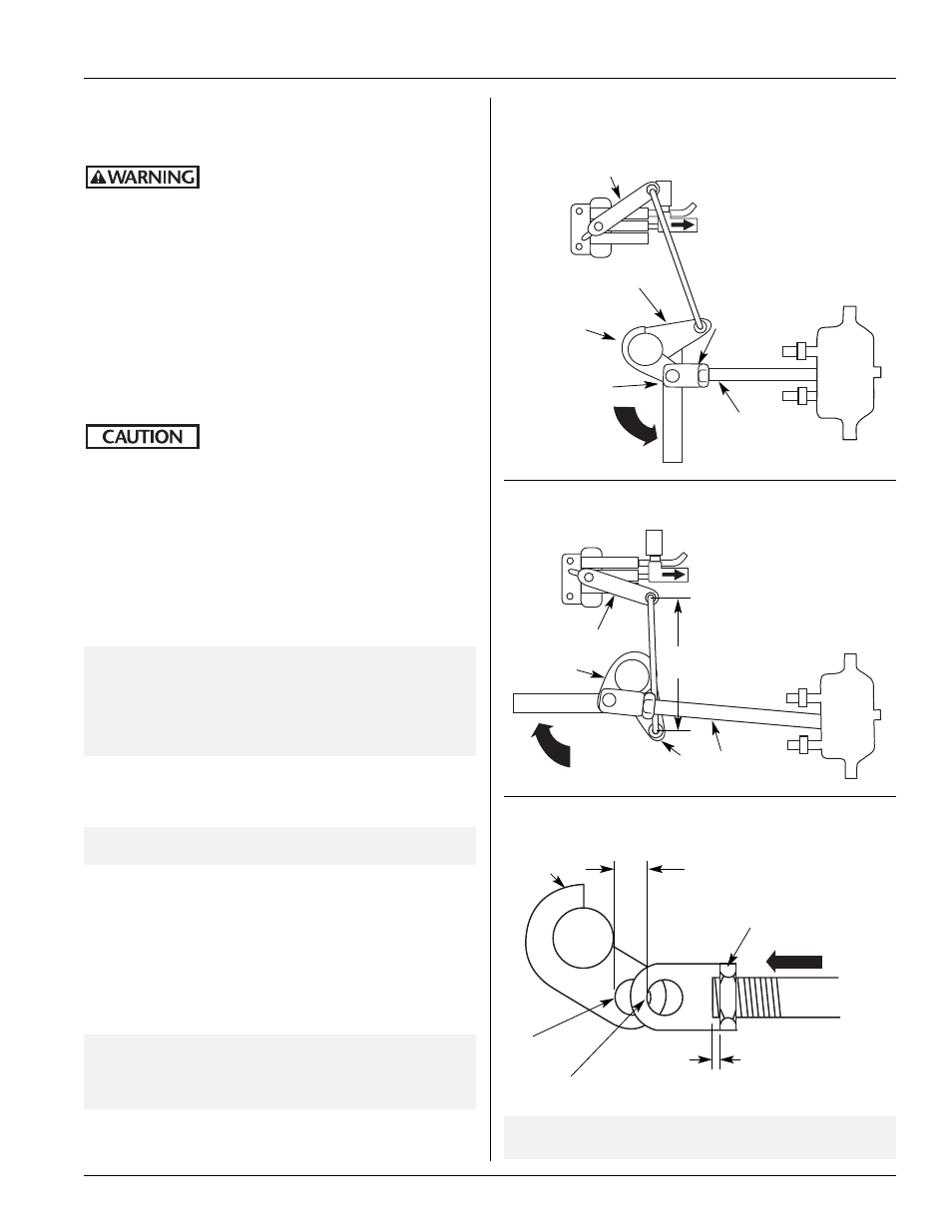
1. With the emergency brakes applied visually check the EDL Flipper
Plates and valve arm for correct positioning (FIGURE 22). If correct
positioning is found move ahead to Step 4.
CORRECT Flipper Plates Engaged (Down) Position
Emergency Brakes APPLIED:
When the EDL is engaged and properly installed/adjusted the valve
arm will be approximately 20˚ above the horizontal position, and
the flipper plates will be in the completely down
position (FIGURE 22).
EDL/ARF System could malfunction if
the flipper plates and sensor valve arm
are not in the correct alignment to each other. If operated
under incorrect alignment—trailer and/or property
damage could result.
2. If upon inspection the flipper plates do not rotate to the complete
down position and the sensor valve arm is not approximately 20˚
above horizontal position, the actuator push rod must be adjusted.
Remove clevis pin, loosen jam nut, and thread the clevis in until the
push rod will pull the EDL flipper plates to the straight down
position and push the valve arm approximately 20˚ above
horizontal position.
IMPORTANT:
When adjusting flipper plates to the straight
down position, clevis must be threaded in 1/2˝
(13mm) short of cam mounting hole (FIGURE
24
). This creates tension on the actuator return
spring to pull the flipper plates completely down
during the engaged application.
3. Pull actuator push rod out so the hole in the cam aligns with the
clevis hole. Install clevis pin and secure with cotter pin
(FIGURE 24). Tighten jam nut against clevis.
NOTE:
Maximum push rod protrusion is 3/16˝ (4.76mm)
(FIGURE 24).
4. With the emergency brakes OFF visually check the EDL flipper
plates and sensor valve arm for correct positioning (FIGURE 23).
CORRECT Flipper Plates Disengaged (UP) Position
Emergency Brakes OFF:
When the EDL is disengaged and properly installed/adjusted the
sensor valve arm will be down approximately 20˚ below horizontal
position and the flipper plates will be in the up position
(FIGURE 23).
IMPORTANT:
If you are unable to obtain either the correct
Engaged or Disengaged positioning, by adjusting
the actuator push rod (FIGURE 22), contact
SAF-HOLLAND Customer Service.
FIGURE 23
CORRECT Flipper Plate Disengaged Position
Auto
Reset
(Sensor)
Valve
EDL
Flipper
Plate
Disengaged (Up) Position
EDL
Actuator
Auto
Reset
(Sensor)
Valve
EDL
Flipper
Plate
Engaged
(Completely Down) Position
EDL
Actuator
FIGURE 22
CORRECT Flipper Plate Engaged Position
Valve Arm down 20˚
(below horizontal)
Actuator
Push Rod
Valve Arm up 20˚
(above horizontal)
Actuator
Push Rod
Leave clevis 1/2˝ (13mm) short of
cam mounting hole to preload
spring in chamber assembly
Adjusting Jam Nut
Clevis Mounting Hole
IMPORTANT:
Flipper plate must be completely down
(engaged position).
Cam
Mounting
Hole
FIGURE 24
EDL Cam to Actuator Push Rod Adjustment
1/2˝
(13mm)
3/16˝ (4.76mm)
Maximum actuator
push rod protrusion
Adjusting
Jam Nut
Clevis
4
3
/
4
˝±1/8˝
(120.65±3.18mm)
Tab
Cam
Cam
Bracket
Cam
Tab