Air system connection, External dock lock (edl) installation – SAF-HOLLAND XL-AR363-02 EDL/ARF Feature User Manual
Page 5
XL-AR363-02 Rev. D
5
EXTERNAL DOCK LOCK (EDL) INSTALLATION
continued
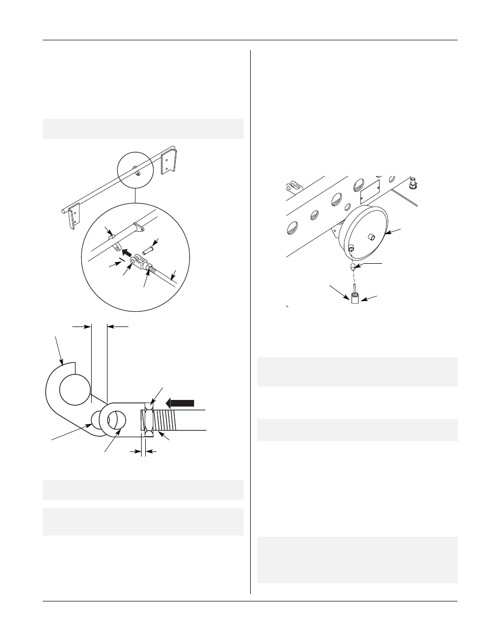
Adjust clevis and jam nut on
push rod so clevis mounting hole
is 1/2˝ (13mm) short of cam
mounting hole to cause tension
on actuator return spring
IMPORTANT:
Flipper Plate must be completely down when
attaching actuator push rod.
Clevis Mounting Hole
Adjusting Jam Nut
Cam Mounting Hole
FIGURE 8
Clevis Installation
Actuator Push Rod
Cam
Bracket
“A”
Cotter
Pin
Cam
Clevis
Adjusting
Jam Nut
Clevis
Pin
Push
Rod
3. Pull actuator push rod out (arrow A) so the hole in the cam aligns
with the clevis hole (this creates tension on the actuator spring to help
keep the flipper plate completely down). Install clevis pin and secure
with cotter pin (FIGURE 8).
IMPORTANT:
Adjust the push rod length to assure flipper plate
is completely down (FIGURE 6).
IMPORTANT:
EDL Rod/Flipper Plate Assembly should rotate
freely without binding after attaching actuator
push rod (FIGURE 6).
Air System Connection
1. The control for releasing the EDL is the same for releasing the
emergency brakes on the trailer. Locate a trailer supply line (usually
red) at the point it enters the spring brake valve (supply port).
2. Replace straight connector fitting with a tee and reconnect the
supply line and add a length of plastic line for connection to the
actuator chamber (FIGURE 9) and the line that you will install which
connects the cylinder port of the pilot valve to the bottom port of
the sensor valve (FIGURE 10).
3. At the threaded end of the 1/4 N.P.T. tube fitting insert the choke
valve (supplied) and install fitting to actuator. Attach the supply line
from the brake valve to a 1/4 N.P.T. tube fitting (FIGURE 9).
NOTE:
It may be necessary to use a vise to press choke valve
into tube fitting or use a hammer and gently tap choke
valve into tube fitting.
4. Insert the 1/4 N.P.T. tube fitting into the brake actuator inlet port
(FIGURE 9).
NOTE:
Choke valve should be flush with bottom of
the fitting.
5. From the pressure protection valve, run a line to the bottom port of
the primary height control valve (FIGURE 12).
6. Connect the top port of the primary height control valve to the
center port of the sensor valve (FIGURE 11).
7. The center ports of the primary height control valve and sensor
valve are connected to the air springs (FIGURE 11).
8. The pilot port of the pilot valve is connected to the emergency line
(FIGURE 12). Secure all supply lines and check for air leaks.
IMPORTANT:
It is the responsibility of the air system installer
to secure all air lines and check for any air leaks.
If air leaks are detected, repair as required.
Failure to eliminate the air leaks may compromise
the suspension performance.
To supply line
connection on
sensor valve
Choke Valve
Actuator
Chamber
FIGURE 9
Connect Air System
Air Line Fitting
3/16˝ (4.76mm)
Maximum actuator
push rod protrusion