Brake shoe replacement – SAF-HOLLAND XL-TA10006OM Drum Brake Axles Tapered and Parallel Spindle Axles User Manual
Page 20
20
XL-TA10006OM-en-US Rev B · 2014-03-13 · Amendments and Errors Reserved · © SAF-HOLLAND, Inc., SAF-HOLLAND, HOLLAND, SAF,
and logos are trademarks of SAF-HOLLAND S.A., SAF-HOLLAND GmbH, and SAF-HOLLAND, Inc.
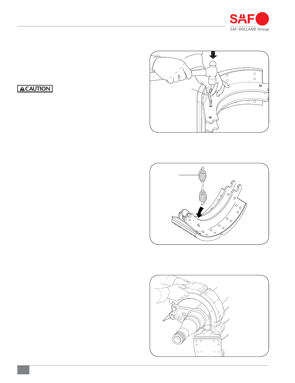
Brake Shoe Replacement
Figure 32
Figure 34
Figure 33
4. Install return spring pin into brake shoe ribs (Figure 32).
5. Connect the hub/drum return spring to the upper and
lower brake shoes (Figure 33).
6. Position the roller of the upper brake shoe up against the
S-Cam, then place the other end of the shoe against the
anchor pin (Figure 34).
Failure to control spring pressure during
brake shoe installation could create a
pinch hazard which, if not avoided, could
result in minor to moderate injury.
RETURN SPRING PIN
UPPER BRAKE SHOE
LOWER BRAKE SHOE
S-CAM
ANCHOR PINS
HUB/DRUM
RETURN SPRING