Amprobe AT-4000 Advanced-Wire-Tracer User Manual
Page 5
3
AT-4000 PRODUCT DESCRIPTION
The AT-4000 consists of two units:
T-4000
Transmitter (32.768KHZ, 9-600 volts AC or DC)
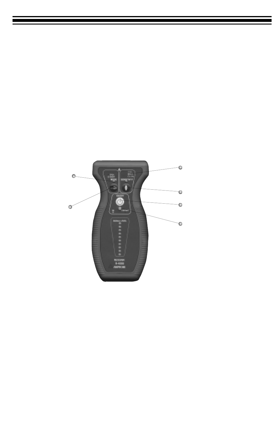
R-4000
Receiver(Non-position sensitive, Open / Short Tracing)
Unit Description
R-4000 Receiver:
It has two built in detectors that are tuned to pick up the 32.768Khz signals generated
by the T-4000 transmitter. The R-4000 is designed to display the signal strength to
enable quick locating of the conductor carrying the signal.
Fig.1 R-4000 Receiver
T-4000 Transmitter
When connected to an energized circuit, the T-4000 will filter the low frequencies up to
400Hz and rapidly indicate on the display that the wire is energized. When the user starts
the transmission, a combination of signals is injected on top of the 50, 60, or 400Hz that
cause a slight, periodic current fluctuation and allows the power line to emit its own,
traceable signal. This signal can be detected back to the main generator. However, the
signal will not interfere with any sensitive electronic equipment and does not require
power interruption. The unit is intrinsically safe and has a ‘LOW’ signal transmission set-
ting that must be used when tracing GFCI-protected circuits.
LED Indicator:
ON-OPEN
OFF-SHORT
LED Indicator:
ON-High Sensitivity
BLINKING - Medium Sensitivity
OFF-Low Sensitivity for breakers
LED Indicator:
Green-Unit ON
Red-Low Battery
Sensitivity Control
Power ON/OFF
Mode Control