Amprobe AT-4000 Advanced-Wire-Tracer User Manual
Page 6
When connecting to a circuit as a load, the signal will be present anywhere between the
T-4000 and the power source. (Line side or Upstream)- no signal will be present on
wiring on the other side of the transmitter(load side or downstream). For example, a
transmitter connected to a circuit breaker will produce no signal on that circuit. It will,
however, cause a signal to be generated between that panel and the transformer…and
beyond. When connecting to an unenergized circuit, the live indication on the display will
remain ‘OFF’. When the user starts the transmission, the transmitter injects a combina-
tion of signals onto the conductor. The signal will travel along the conductor until it ends.
There is no difference in the functional mode of the unit when tracing energized circuit
and unenergized circuits. On an open line, no current will flow, so the injected signal will
present itself as a voltage spike along the wire which is detected by the R-4000 in the
‘OPEN’ mode. When the conductor is part of a complete circuit, the voltage causes a
current to flow which produces a signal that is detected in the ‘SHORT’ mode. The
T-4000 contains a 9V battery. A 24V input jack accepts the B2024 rechargeable battery
or the B2025 110V converter, both use when a very strong signal is necessary.
(Note: When using the battery booster (B2024 or B2025) the unit will work in ultra
high “U-HI” mode only. Remove the battery booster to return to normal operation.)
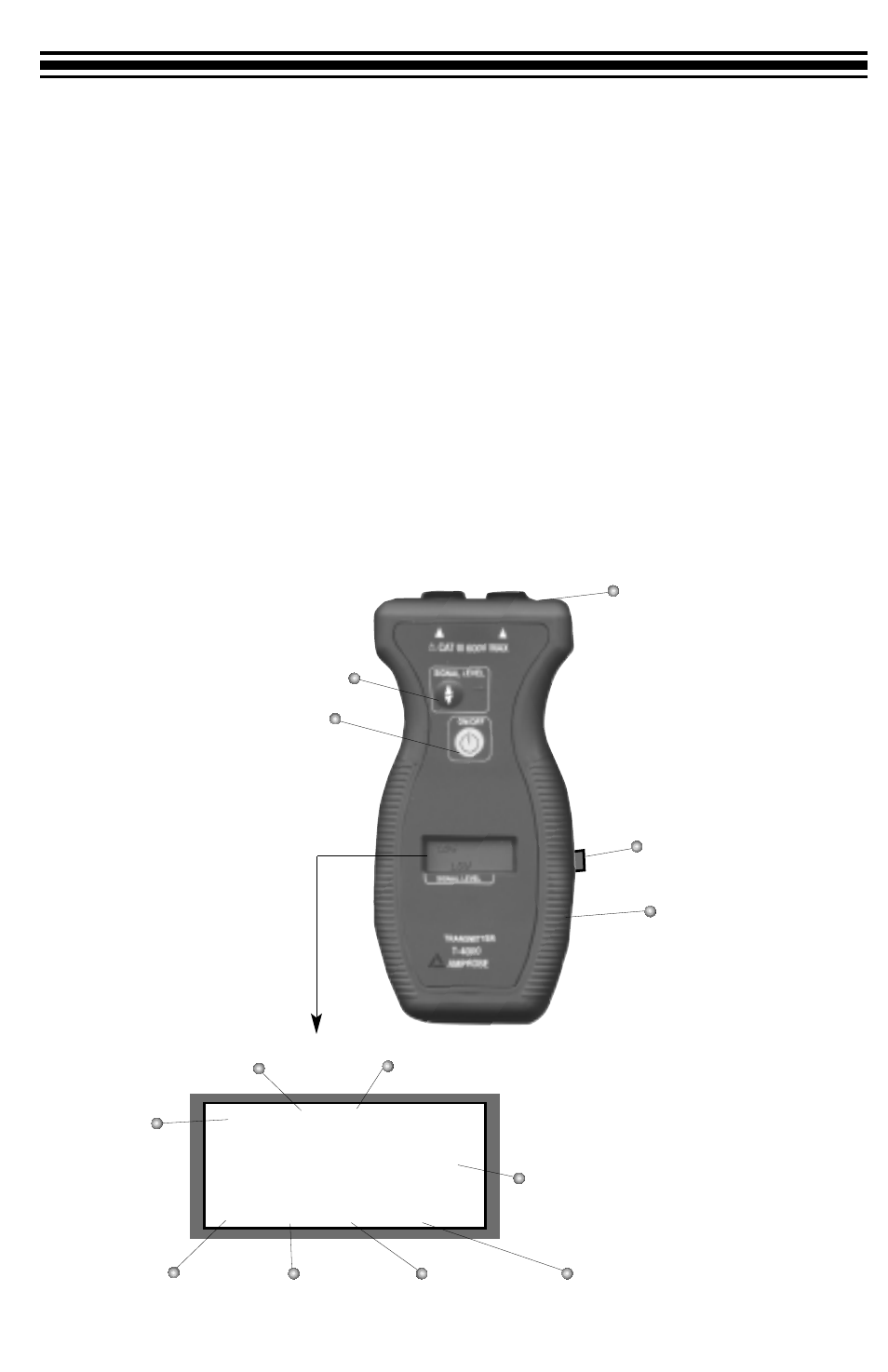
Fig.2 T-4000 Transmitter
4
Fuse (inside) Holder
Power ON/OFF
Banana Plug Jack
Signal Level Switch
(Energized Line) Live
Transmission OFF
Transmission LOW
Transmission HIGH
Transmission MEDIUM
LCD Display
24 Volt Jack
SET (select a signal level)
9V Battery Compartment
Low Battery
18888
q
LIVE SET VOP M
OFF LOW MID HIGH FT