Amprobe AT-7000 User Manual
Page 18
14
3.1 Tracing Energized Wires
TIP SENSOR
TIP SENSOR mode is used for the following
applications: pinpointing a wire in a bundle,
tracing in corners and confined spaces such as
junction boxes or inside enclosures.
Connecting transmitter test leads
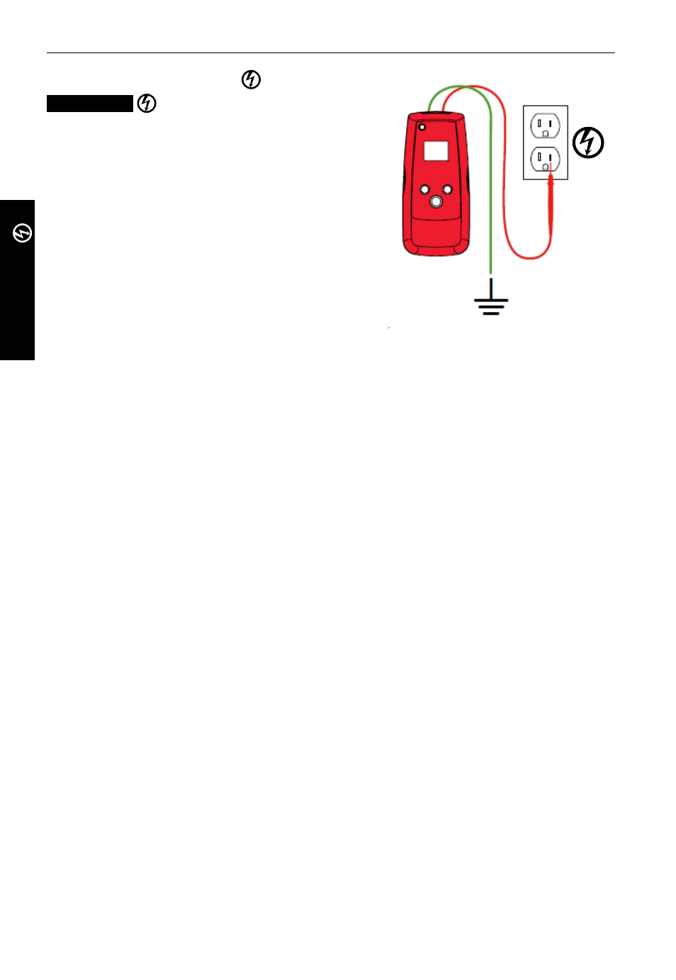
1. Connect green and red test leads to the
transmitter (polarity does not matter)
2. Connect red lead to energized hot wire (on
the load side of the system).
The signal will ONLY be transmitted between
the outlet to which the transmitter is
connected and the source of power (see
Figure 3b).
3. Connect green wire to a separate ground
(metal building structure, metal water pipe,
or ground wire on a separate circuit).
*Note: Please note that if working with GFCI protected circuits, this method will trip the
GFCI protection. Refer to Special Applications, section 4.1 “GFCI-Protected Circuit Wire
Tracing” for alternative tracing methods.
Set up the AT-7000-T Transmitter:
1. Press ON/OFF key to turn on the transmitter.
2. Verify that the test leads are properly connected - the red LED voltage status should
indicator should be on, indicating that the circuit is energized. If not, make sure that
• the circuit is energized
• the separate ground green wire is properly grounded. If the ground wire is not
properly grounded the red LED will not light, even when connected to an energized
circuit.
3. Select HIGH signal mode for most applications. Screen will appear as shown in Figure
3.1b.
Note: The LOW signal precision mode can be used to limit the signal level generated by the
transmitter in order to more precisely pinpoint wire location. A lower signal level reduces
coupling to neighboring wires and metal objects and helps to avoid misreading due to
ghost signals. A lower signal also helps to prevent oversaturating the receiver with a
strong signal that covers a large area. The LOW mode function is rarely used, only for most
demanding precise wire tracing applications.
3. main aPPLications - tiP sensor (energized)
TIP SENSOR
Figure 3.1f
Proper connection with separate ground