Special applications – Amprobe AT-7000 User Manual
Page 30
26
4.10 No Access to Bare Conductors (Signal Clamp)
The clamp accessory is used for applications where there is no access to the bare conductor
to connect transmitter test leads. When clamp is connected to the transmitter, it enables the
AT-7000-T to induce signal to energized or de-energized wire through the insulation. The
signal will travel through the wire both directions and it will affect all the branches. This
method is safe to use for any sensitive electronic equipment.
Connect the clamp
1. Connect the SC-7000 test leads to the
terminals of the transmitter
(polarity does not matter).
2. Clamp the SC-7000 Signal Clamp around the
conductor. To increase the signal strength
wind a few turns of conductor wire around
the clamp if possible.
Set up the AT-7000-T Transmitter:
1. Press ON/OFF key to turn on the transmitter. The red LED voltage status indicator should
be OFF when clamp is connected and when working with either energized or de-
energized systems.
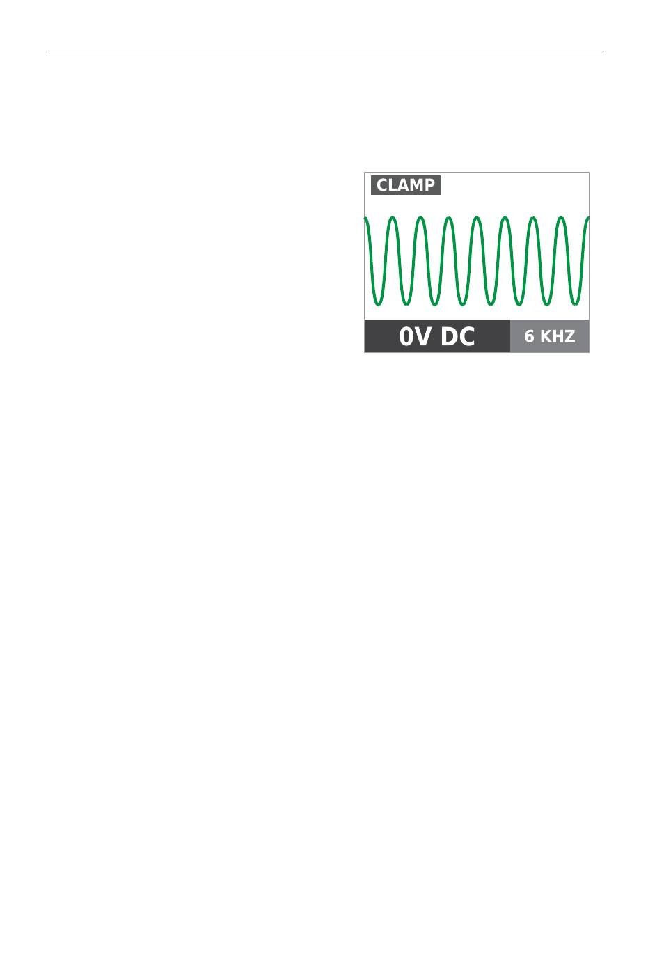
2. Press HIGH signal mode for 2 seconds to select the clamp mode on the transmitter. The
clamp mode generates a boosted 6kHz signal in order to provide superior tracing results.
The screen on the Transmitter should appear as in Figure 4.10a.
Using AT-7000-R Receiver
1. Press ‘ON/OFF’ push button to turn on the receiver and wait for the home screen (boot
up time is around 30 seconds).
2. Select Energized TIP SENSOR mode by using the directional arrows to highlight this
operating mode and pressing the yellow “ENTER” button.
3. Hold the receiver with the Tip Sensor facing the target area.
4. Scan target area with Tip Sensor to find highest signal level. While tracing, periodically
adjust sensitivity to keep signal strength near 75. Increase or decrease sensitivity by
pressing +or – on the keypad.
5. Receiver Positioning: For best results, align groove on tip sensor with wire direction as
shown. Signal may be lost if not properly aligned.
6. To verify wire direction, periodically rotate receiver 90 degrees. Signal strength will be
highest when wire is aligned with Tip Sensor groove.
4. sPeciaL aPPLications
Figure 4.10a
Transmitter in CLAMP mode