Switching in switcher mode, Cher mode (p. 15), P. 15 – Roland XS-1HD Multi-Format Matrix Switcher User Manual
Page 15: De (p. 15), P. 15), the output, Cher mode (p. 15, Operating procedure, Output example, 15 video operations, Compositing with pinp or key
15
Video Operations
Switching in Switcher Mode
The video of the PGM side (XPT3 row) is always output. The PST side (XPT4 row) selects the preset video (the
video that will be output next). Use the [AUTO] button or operate the video fader to switch the video.
Operating procedure
1.
As described in “Switching the screen mode”
(p. 12), set the screen mode to Switcher.
2.
Move the video fader all the way in one or the
other direction.
3.
Press a PST (XPT4 row) cross-point button to
select the preset video (the video that you want
to show next).
Lit red: Final output video (PGM)
Lit green: Preset video (PST)
4.
Use the [TIME] knob to specify
the video transition time.
5.
Press the [AUTO] button.
A dissolve effect is applied, and
the output video is switched.
When the transition between
videos is completed, the
illumination of the PGM and PST
buttons is exchanged.
5
When using the video fader to switch, move the video
fader in the opposite direction that you did in step 2.
When the video fader is moved all the way, the videos
are switched completely.
Compositing with PinP or key
Here’s how to composite videos using PinP. You can
also key-composite the PinP inset video.
1.
Press the [MENU] button
g
“Composition”
g
set “Mode” to “PinP & Key.”
If you want to use key-compositing, set
“Composition”
g
“Setup”
g
“Key” to “Enabled.”
Also set “Type” to specify the key type (the color
to be removed).
2.
Press a cross-point button in the XPT2 row to
select the video that will be the inset screen.
The color in which the button is lit indicates the
output destination of the composited result.
Lit green
Preview output only
Lit red
Final output, preview output
5
When you press a cross-point button that is lit green, it
changes to being lit red, and the composited result is the
final output.
5
When you press a cross-point button that is lit red, it
changes to being lit green, and the composited result
output is only the preview.
MEMO
5
To adjust the position, size, and keying depth of the
inset screen, press the [MENU] button
g
“Composition”
g
“Setup”
g
[ENTER] button
g
adjust the various PinP
Window and Key settings.
5
You can also use the quick edit function to adjust the
position, size, and keying depth of the inset screen (p. 19).
Using the AUX bus
Here’s how you can assign the AUX bus to the VIDEO
OUTPUT 3 connector.
1.
Press the [MENU] button
g
“Composition”
g
set “Mode” to “AUX.”
2.
Press a cross-point button in the XPT2 row to
select the video that is sent to the AUX bus.
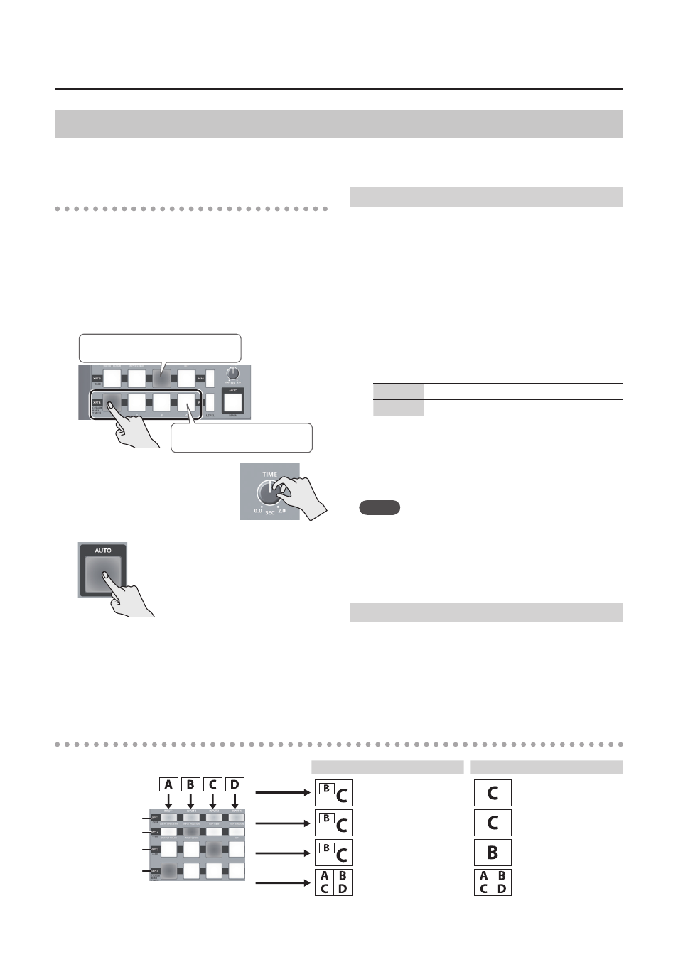
Output example
INPUT
PinP/key, AUX
Final output video
Preset video
(Not used.)
When the Mode = PinP & Key
When the Mode = AUX
OUTPUT 1
Final output video
Final output video
OUTPUT 2
Preview the PinP or
key-composited result
Final output video
OUTPUT 3
Final output video
AUX bus video
OUTPUT 4 (*1)
Show the input videos
in separate quarters
Show the input videos
in separate quarters
(*1) The frame rate will decrease to approximately 5 fps.
Tally frame is shown
Tally frame is shown