Editing a sound (program), Editing an analog part, Y (p. 5) – Roland JD-XA Analog/Digital Synthesizer User Manual
Page 5
5
Editing a Sound (Program)
Editing an Analog Part
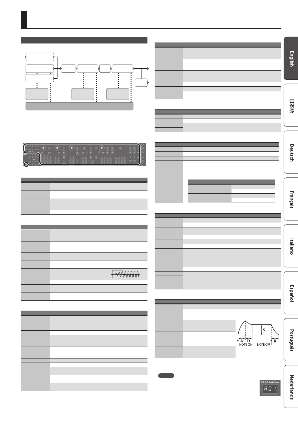
ANALOG PART
HPF
DRIVE
A-OSC1
AUX
A-OSC2
Pitch ENV
1/2
A-Filter
Filter ENV
AMP
AMP ENV
LFO 1/2
MFX
DRY
OUT
&
For details of the overall structure, refer to the “JD-XA Structure Diagram”
inside the front cover.
When you move a controller, the corresponding parameter is shown in the screen
(the value changes in tandem with the controller).
If you move the controller while holding down the [Exit] button, the parameter is
displayed without changing its value; this lets you check the current value.
ANALOG PART
Controller
Explanation
Select [01]–[04]
buttons
Select the part that is edited by panel operations.
On [01]–[04]
buttons
Select the part that is played from the keyboard.
[Poly Stack] button
Lets you use the four analog parts as one four-voice poly part.
If the Poly Stack is on, only one part is on.
Use the On [01]–[04] buttons to select the parts that are used for poly stack.
[Unison] button
Selects unison. This is available only if poly stack is on.
LFO
Controller
Explanation
Wave knob
Selects the LFO waveform.
S
(Triangle wave),
R
(Sine wave),
T
(Sawtooth wave),
U
(Square wave),
W
(Sample and Hold),
RND
(Random wave)
[Rate] knob
Determines the speed of the LFO modulation.
* If the [Tempo Sync] button is on, you can specify the LFO modulation
speed in terms of a note value relative to the tempo.
[Select] button
Selects the LFO that will be edited.
LFO1 (unlit), LFO2 (lit)
[Tempo Sync]
button
Synchronizes the LFO modulation speed to the tempo.
[Fade Time] slider
Specifies the time from when the tone
sounds until the LFO reaches its maximum
amplitude.
[Pitch Depth] slider
Allows the LFO to modulate the A-OSC pitch, producing a vibrato effect.
[Filter Depth] slider
Allows the LFO to modulate the FILTER CUTOFF (cutoff frequency),
producing a wah effect.
[Amp Depth] slider
Allows the LFO to modulate the AMP LEVEL (volume), producing a tremolo
effect.
A-OSC1
Controller
Explanation
Wave knob
Selects the oscillator waveform.
T
(Sawtooth wave),
U
(Square wave),
V
(Asymmetrical square wave),
S
(Triangle wave),
R
(Sine wave),
Variation (not used with A-OSC)
[Variation] button
Not used with analog parts.
[PWM] slider
When
V
(asymmetrical square wave) is selected as the oscillator
waveform
Specifies the amount of LFO modulation applied to PW.
[PW] slider
When
V
(asymmetrical square wave) is selected as the oscillator
waveform
Specifies the pulse width.
[Pitch] knob
Specifies the oscillator pitch.
[Fine] knob
Fine adjustment of the oscillator pitch.
[Cross Mod] knob
Specifies the amount by which the A-OSC2/AUX waveform modifies the
frequency of A-OSC1.
[Ring Mod] button
Gives the sound a metallic character by multiplying A-OSC1 and A-OSC2/
AUX.
[Mod Source]
button
Selects the modulation source waveform (A-OSC2/AUX).
A-OSC2
Controller
Explanation
Wave knob
Selects the oscillator waveform.
T
(Sawtooth wave),
U
(Square wave),
V
(Asymmetrical square wave),
S
(Triangle wave),
R
(Sine wave),
[PWM] slider
When
V
(asymmetrical square wave) is selected as the oscillator
waveform
Specifies the amount of LFO modulation applied to PW.
[PW] slider
When
V
(asymmetrical square wave) is selected as the oscillator
waveform
Specifies the pulse width.
[Pitch] knob
Specifies the oscillator pitch.
[Fine] knob
Fine adjustment of the oscillator pitch.
[OSC Sync] button
Creates a complex waveform by forcibly returning A-OSC1 to the beginning
of its cycle in synchronization with the cycle of A-OSC2.
PITCH ENV
Controller
Explanation
[Depth] knob
Specifies the direction and amount of the pitch change.
[Select] button
Selects the pitch envelope editing target.
[A] slider
These sliders operate similarly to the [A] [D] sliders of the AMP section (they
affect the pitch rather than the volume).
[D] slider
MIXER
Controller
Explanation
[A-OSC 1] knob
Specifies the A-OSC1 volume.
[A-OSC 2] knob
Specifies the A-OSC2 volume.
[AUX] knob
Specifies the AUX volume.
[Select] button
Specifies the AUX source.
White Noise, Pink Noise, Digital Part, MIC
* The digital part that can be selected as the AUX source will be the same
part number as the analog part. It is not possible to select a different
part.
Analog part
Digital part selected
Analog part 01
Digital part 01
Analog part 02
Digital part 02
Analog part 03
Digital part 03
Analog part 04
Digital part 04
FILTER
Controller
Explanation
[HPF] knob
Specifies the cutoff frequency of the high-pass filter.
[Drive] knob
Adjusts the drive.
Filter type select
knob
Selects the filter type.
LPF1–3 (Low Pass Filter), HPF (High Pass Filter), BPF (Band Pass Filter)
[Variation] button
Not used with analog parts.
[Cutoff] knob
Specifies the cutoff frequency.
[Resonance] knob
Specifies the resonance.
[Key Follow] knob
Allows the filter cutoff frequency to vary according to the key that you play.
If the knob is turned toward the right, the cutoff frequency becomes higher
as you play higher notes.
If the knob is turned toward the left, the cutoff frequency becomes lower as
you play lower notes.
[ENV Depth] knob
Specifies the direction and amount of the change in cutoff frequency.
[A] slider
These sliders operate similarly to the [A] [D] [S] [R] sliders of the AMP section
(they affect the cutoff frequency rather than the volume).
[D] slider
[S] slider
[R] slider
AMP
Controller
Explanation
[Level] knob
Specifies the AMP Level.
[A] slider
(Attack time)
Specifies the time from the moment
you press the key until the maximum
volume is reached.
[D] slider
(Decay time)
Specifies the time from when the
maximum volume is reached, until it
decays to the sustain level.
[S] slider
(Sustain level)
Specifies the volume level that will be
maintained from when the attack and
decay times have elapsed until you
release the key.
[R] slider
(Release time)
Specifies the time from when you
release the key until the volume reaches
its minimum value.
EFFECTS
&
MEMO
5
If the program has been edited, the decimal point of the program
number is lit.
5
The edited sound is saved in the program.
&
“Saving a Program (Write)” (p. 7)
5
Some parameters can be edited without using a controller.
&
For details, refer to “Parameter Guide (English)” (PDF).