Environmental performance, Fibers and connectors, Pin connector – Approved Optics Approved HP J9144A User Manual
Page 5: Regulatory compliance, Rail and mechanical mounting requirements, J9144a-a
Page 5 of 8
Approved Optics
www.ApprovedOptics.com
J9144A-A
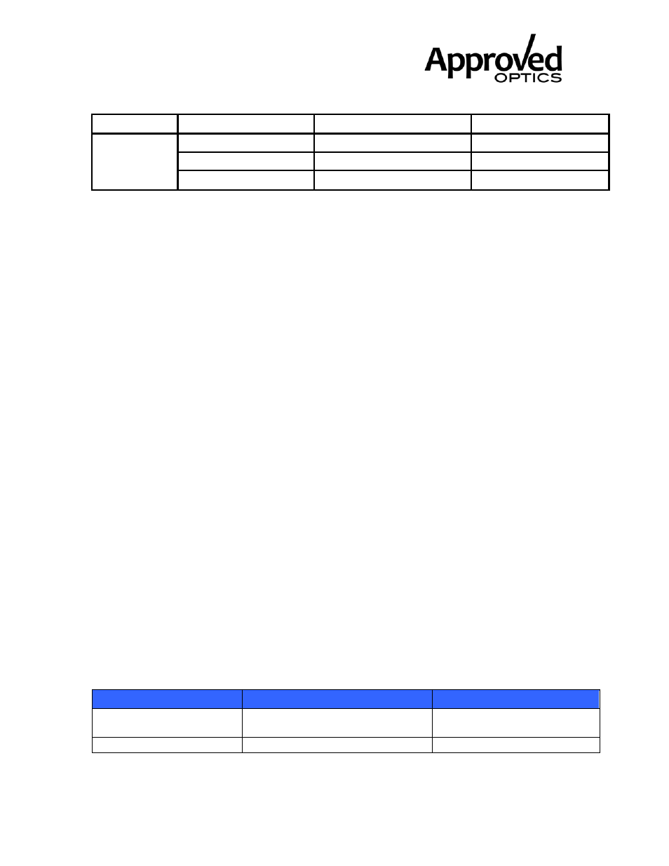
X2-LRM 10GB Module
1310nm, 220m, MMF, SC RoHS6
50 µm MMF
400
100
Fibre
Channel
62.5 µm MMF
200
220
50 µm MMF
500
220
50 µm MMF
2000
220
Notes:
1) Operating range as defined by IEEE and Fibre Channel standards. Longer reach possible
depending upon link implementation.
Environmental Performance
Operating case temperature:
0°C to +70°C
Operating humidity:
0% -95% RH non-condensing
Fibers and Connectors
The transponder has SC receptacles for both Tx and Rx. The transponder is designed
for multimode SC cables, 0° polished endface (PC).
70-pin Connector
The module interface connector is a 70-pin, printed circuit board edge connection with a 0.5
mm pitch. The appropriate mating connector for the customer PCB is a 70-pin SMT, dual
row, right angled, edge connector, 0.5 mm pitch (Tyco Electronics part number 1367337-1,
Molex part number 74441-0003 or equivalent).
Rail and Mechanical Mounting Requirements
The X2 rail system required to mount the X2 module is fully defined by the MSA. (Tyco
Electronics part number 1367608-1: designed for belly to belly applications; and 1367610-1,
designed for single sided board mount to fit into the standard host PCB footprint; or
equivalent). For further details please refer to vendor-supplied information.
Regulatory Compliance
Feature
Standard
Comments
ESD: Electrostatic
Discharge to the
EIA/JESD22-A114-B (MIL-STD
883D
Class 1a (> 500 V)
Electrical Pins (HBM)
Method 3015.7)