Zabg6002, Application information – Diodes ZABG6002 User Manual
Page 7
ZABG6002
ZABG6002
Document number: DS32078 Rev. 1 - 2
7 of 12
May 2010
© Diodes Incorporated
A Product Line of
Diodes Incorporated
Application Information
The ZABG6002 is a flexible device and can be set up in a number of ways.
1. 6 LNA stages to provide standard bias to the GaAs or HEMT FET’s
2. 4 LNA stages to provide standard bias to the GaAs or HEMT FET’s plus 2 active mixer stages
3. Power down FET groups for LNA switching or power saving.
The truth table below shows the function of these features.
FET Stage
R
cal
Pin Resistor Termination
1st LNA
Stages
2nd LNA
Stages
3rd LNA/Mixer
Stages
Rcal1 Rcal2 RcalM Bias
1 Bias
4
Bias 2
Bias 5
Bias 3
Bias 6
Gnd
Gnd
Open
On On On On On On
Gnd
Gnd
Gnd On On On On
Mixer
Mixer
Gnd 3V
Open
On On Off Off Off Off
Gnd 3V Gnd On On Off Off
Mixer
Mixer
3V Gnd
Open
Off Off On On On On
3V Gnd
Gnd Off Off On On
Mixer
Mixer
3V 3V
Open
Off Off Off Off Off Off
3V 3V Gnd Off Off Off Off
Mixer
Mixer
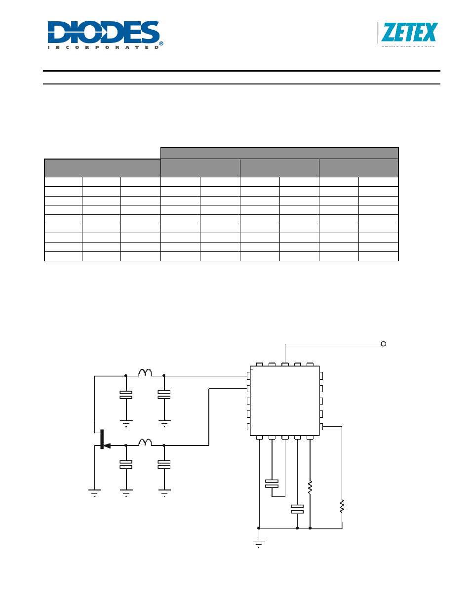
ZABG6002 in 6 LNA mode
Below is a partial applications circuit for the ZABG6002 showing all external components needed for biasing one of
the six FET stages available as a normal LNA bias. Each bias stage is provided with a gate and drain pin. The drain
pin provides a regulated 2.0V supply that includes a drain current monitor. The drain current taken by the external
FET is compared with a user selected level, generating a signal that adjusts the gate voltage of the FET to obtain
the required drain current. If for any reason, an attempt is made to draw more than the user set drain current from
the drain pin, the drain voltage will be reduced to ensure excess current is not taken. The gate pin drivers are also
current limited.
The bias stages are split up into two groups, with the drain current of each group set by an external R
CAL
resistor.
R
CAL
1 sets the drain currents of stages 1 and 4, whilst R
CAL
2 sets the drain currents of stages 2,3,5 and 6.
JF2
Vcc
L*
L*
C*
C*
C1
10nF
C2
10nF
CNB
47nF
CSUB
47nF
RCAL2
* Stripline Elements
RCAL1
36k
G2
Gn
d
D3
G3
Cnb
1
G1
D4
Vc
c
D1
D5
D2
G5
C
nb2
Cs
u
b
D6
G6
Rc
al
2
Rcal1
RcalM
G4
ZABG6002
JF2
Vcc
L*
L*
C*
C*
C1
10nF
C2
10nF
CNB
47nF
CNB
47nF
CSUB
47nF
RCAL2
* Stripline Elements
RCAL1
G2
Gn
d
D3
Cnb
1
G1
D4
Vc
c
D1
D5
D2
G5
C
nb2
Cs
u
b
D6
G6
Rc
al
2
Rcal1
RcalM
G4
ZABG6002
36k